In this article, I’ll show you how to program the Arduino to control the on-board LED with a push button. I’ll also show you a program that changes the LED’s blink rate depending on how much light hits a photoresistor. At the end of the tutorial, I’ll show you how to use the photoresistor to vary the pitch of sound output by a speaker. This tutorial is part three of a series on the basics of getting started with the Arduino. Part one of the series can be found here.

Controlling the Arduino’s LED with a Push Button
Each one of the Arduino’s GPIO (General Purpose Input/Output) pins can be programmed to act as either an input or an output. As inputs, pins read electrical signals sent from other devices, and as outputs they send signals to other devices.
In this project, we’ll write a program that will define a pin as an input. Then we’ll connect a push button to it. When the button is pressed, the Arduino will send a signal to an output pin to make an LED turn on and off.
It’s pretty easy to do as you’ll see in the diagram and code below.
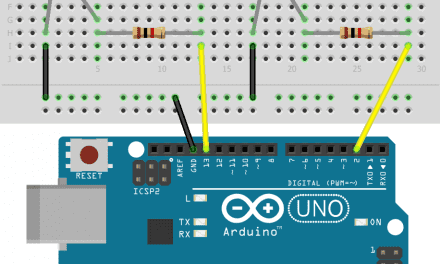
First, connect a 1K Ohm resistor and a push button to the Arduino like this:
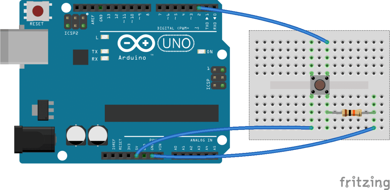
Now, enter this code into the Arduino IDE and upload it to the board:
const int ledPin = 13;
const int inputPin = 2;

void setup(){
  pinMode(ledPin, OUTPUT);
  pinMode(inputPin, INPUT);
}

void loop(){
  int val = digitalRead(inputPin);
  if (val == HIGH){
  digitalWrite(ledPin, HIGH);
  }
  else{
    digitalWrite(ledPin, LOW);
  }
}
The Arduino’s pin 13 LED should light up when the push button is pressed, and turn off when the button is released.
How the Program Works
The code pinMode(ledPin, OUTPUT); defines pin 13 as an output pin and gives it the name ledPin.
The code pinMode(inputPin, INPUT); defines pin 2 as an input pin and gives it the name inputPin.
You can change the input and output pins to any other available GPIO pin by simply changing the pin numbers on lines 1 and 2 of the program above.
The digitalRead(inputPin) statement tells the Arduino to listen to the inputPin (pin 2) for any signals that might be sent to it.
if (val == HIGH) tells the Arduino to listen for a HIGH signal at the inputPin, which will happen when the push button is pressed. If a HIGH signal is detected, digitalWrite(ledPin, HIGH); will make the Arduino send an output signal to the ledPin (pin 13), making the LED light up.
The else statement tells the Arduino to set the voltage at the ledPin to LOW if the signal at the inputPin is LOW. The signal at the inputPin will be LOW as long as the button is not pressed.
Controlling the Arduino’s LED with a Photoresistor
A photoresistor is a light sensitive resistor that changes resistance depending on how much light hits it. The resistance decreases with more light, and increases with less light.
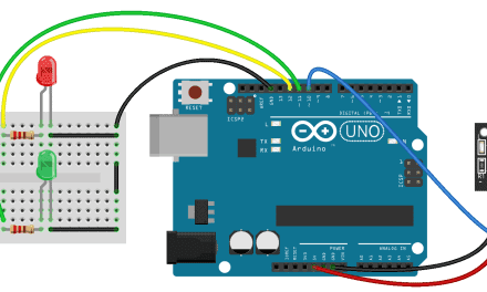
We can use the Arduino to detect the resistance of the photoresistor and use that value to control the blink rate of an LED. Start by connecting a photoresistor and a 1K Ohm resistor to the Arduino like this:
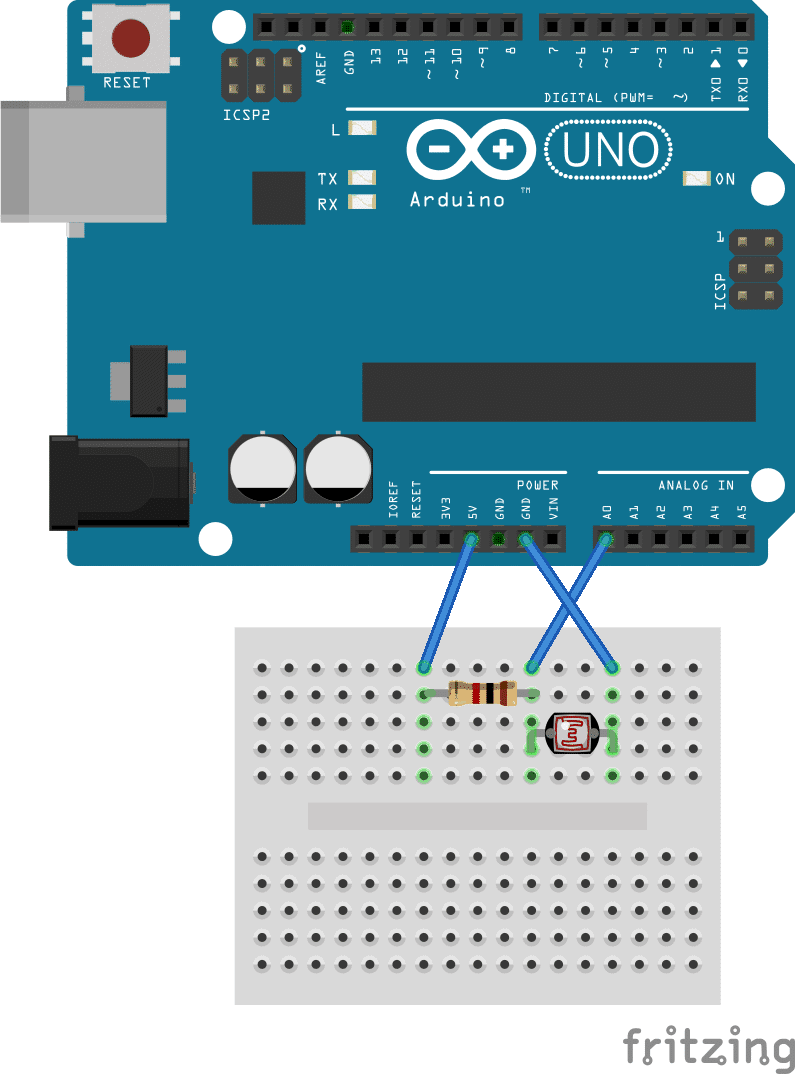
Enter this code into the Arduino IDE and upload it to the Arduino:
const int ledPin = 13;
const int sensorPin = 0;
const int minDuration = 100;
const int maxDuration = 1000;

void setup(){
  pinMode(ledPin, OUTPUT);
}

void loop(){
  int rate = analogRead(sensorPin);
  rate = map(rate, 200, 800, minDuration, maxDuration);
  digitalWrite(ledPin, HIGH);
  delay(rate);
  digitalWrite(ledPin, LOW);
  delay(rate);
}
Now wave your hand over the photoresistor, and you should see that the LED flashes faster when your hand is covering the photoresistor.
How the Program Works
First we define the output pin (pin 13) and input pin (analog pin 0) with these two statements:
const int ledPin = 13;const int sensorPin = 0;
We want each individual flash of the LED to be long when lots of light hits the photoresistor. When no light hits the photoresistor, we want the LED flashes to be short. We define the minimum and maximum duration of the flashes on lines 3 and 4. Line 3 sets the minimum duration (minDuration) at 100 ms, and line 4 sets the maximum duration (maxDuration) at 1000 ms.
int rate = analogRead(sensorPin); tells the Arduino to read the resistance of the photoresistor at the sensorPin (pin 0) and to store the detected value in a variable called rate.
The Arduino reads the resistance of the photoresistor and assigns it a value between 200 and 800. The lowest resistance is given a value of 200, and the maximum resistance is given a value of 800.
rate = map(rate, 200, 800, minDuration, maxDuration); says to define a range of resistance values (from 200 to 800) and map them to the range of minDuration and maxDuration values (from 100 ms to 1000 ms). That way, when the detected resistance has a value of 200, the rate value will correspond to the minDuration value of 100. When the detected resistance has a value of 800, the rate value will correspond to the maxDuration value of 1000 ms. All values of resistance from 200 to 800 will be mapped to duration values between 100 ms and 1000 ms.
The delay(rate) functions in the void loop() section first tell the Arduino to send a HIGH signal to the ledPin for the duration of the rate value. Next, a LOW signal is sent to the ledPin for the duration of the rate value. This produces the on/off flashing effect.
Controlling Audio Pitch with a Photoresistor
This project is similar to the previous project where we used the photoresistor to control the rate of flashing of the Arduino’s LED. However now we’ll use the photoresistor to control the audio frequency emitted by a passive speaker. The only difference in the code here is that we will change the rate of the output signal.
First, connect a 1K Ohm resistor and a passive speaker to the Arduino like this:
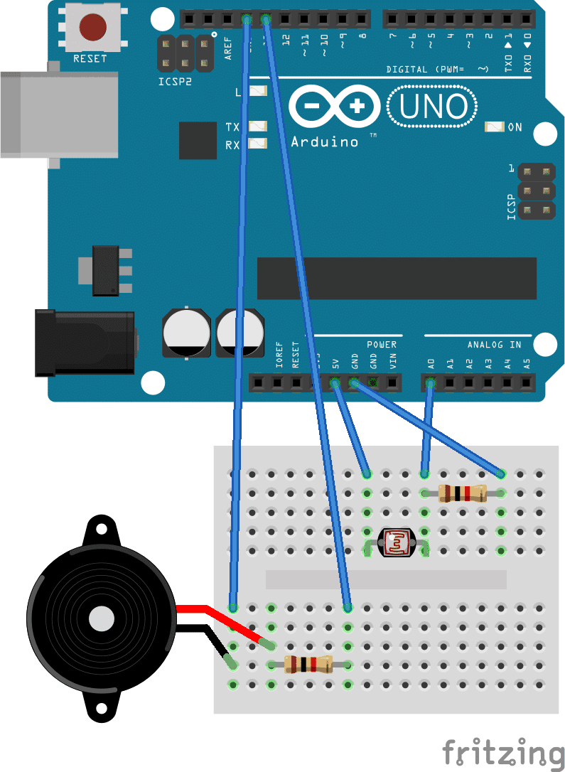
Then, enter this code into the Arduino IDE and upload it to the board:
const int ledPin = 13;
const int sensorPin = 0;
const int minDuration = 100;
const int maxDuration = 1000;

void setup(){
 pinMode(ledPin, OUTPUT);
}

void loop(){
 int sensorReading = analogRead(sensorPin);
 int rate = map(sensorReading, 200, 800, minDuration, maxDuration);
 rate = rate / 100;
 digitalWrite(ledPin, HIGH);
 delay(rate);
 digitalWrite(ledPin, LOW);
 delay(rate);
}
Now wave your hand over the photoresistor and notice how the pitch output by the speaker increases as the light hitting the photoresistor decreases.
That about wraps up this series on getting started with the Arduino. If you want to learn more, be sure to check out our other tutorials on projects like connecting an LCD, setting up an ultrasonic range finder, or using a humidity and temperature sensor with the Arduino.
Check out this project, and I’ll show you how to use a chip called the 555 timer to produce this same effect.
Feel free to leave a comment below if you need help setting the circuit or if you have any questions! And be sure to subscribe to get an email notification when we publish new tutorials…


very good!
nice.
Hello maybe I do something wrong but is isn’t working for me. I made the last one but when i wave my hand over it is does nothing and i have to reset my arduino. I copied your code
I want to use this code to make a smart walking stick
with the second project my led flashes slower as I move my hand over.. same code same wiring i think! very confusing
I also got the same result.
more light = faster flashes while less light = slower flashes.