In this tutorial, I’ll show you how to use an Arduino to control LEDs. This is a pretty simple project, but you should learn how to do it early on because lots of other sensors and modules are programmed the exact same way.

First I’ll show you how to turn on and off the Arduino’s on-board LED. Then I’ll show you how to turn on and off an LED connected to one of the Arduino’s digital pins. I’ll explain how to change the LEDs flashing rate, and how to change the pin that powers the LED. At the end I’ll show you how to control multiple LEDs. Before starting, you should have the Arduino IDE software installed on your computer.
Electrical Signals
The Arduino communicates with modules and sensors by switching on and off electrical current. It’s very similar to the one’s and zero’s in binary code. When current is switched on, it’s known as a “HIGH signal”. That’s comparable to the “one” in binary code. When the current is switched off, that’s a “LOW signal”, which is similar to the zero in binary code. The length of time the current stays on or off can be changed from a microsecond up to many minutes.
Watch the video for this tutorial:
Controlling the Arduino’s LED
To turn on an LED, the Arduino needs to send a HIGH signal to one of it’s pins. To turn off the LED, it needs to send a LOW signal to the pin. You can make the LED flash by changing the length of the HIGH and LOW states.
The Arduino has an on-board surface mount LED that’s hard wired to digital pin 13. It’s the one with an “L” next to it:
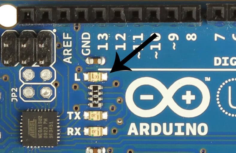
To get this LED flashing, upload the “Blink” program to your Arduino:
void setup() {
  pinMode(13, OUTPUT);
}
void loop() {
  digitalWrite(13, HIGH);
  delay(1000);
  digitalWrite(13, LOW);
  delay(1000);
}
The LED should now be blinking on and off at a rate of 1000 milliseconds (1000 milliseconds = 1 second).
The delay() function on line 6 tells the Arduino to hold the HIGH signal at pin 13 for 1000 ms. The delay() function on line 8 tells it to hold the LOW signal at pin 13 for 1000 ms. You can change the blinking speed by changing the number inside the parentheses of the delay() functions.
Controlling an External LED
An external LED or any other powered module can be controlled in a similar way.
LEDs need to have a resistor placed in series (in-line) with it. Otherwise, the unrestricted current will quickly burn out the LED. The resistor can be any value between 100 Ohms and about 10K Ohms. Lower value resistors will allow more current to flow, which makes the LED brighter. Higher value resistors will restrict the current flow, which makes the LED dimmer.
Also, most LED’s have polarity, which means that they need to be connected the right way around. Usually, the LED’s shortest lead connects to the ground side.
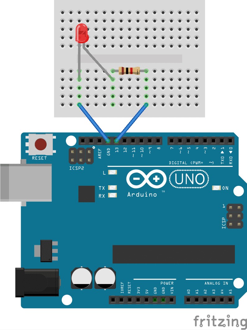
If you connect the LED to pin 13 as shown in the image below, you can use the same code we used above to make the LED flash on and off.
Changing the Pin
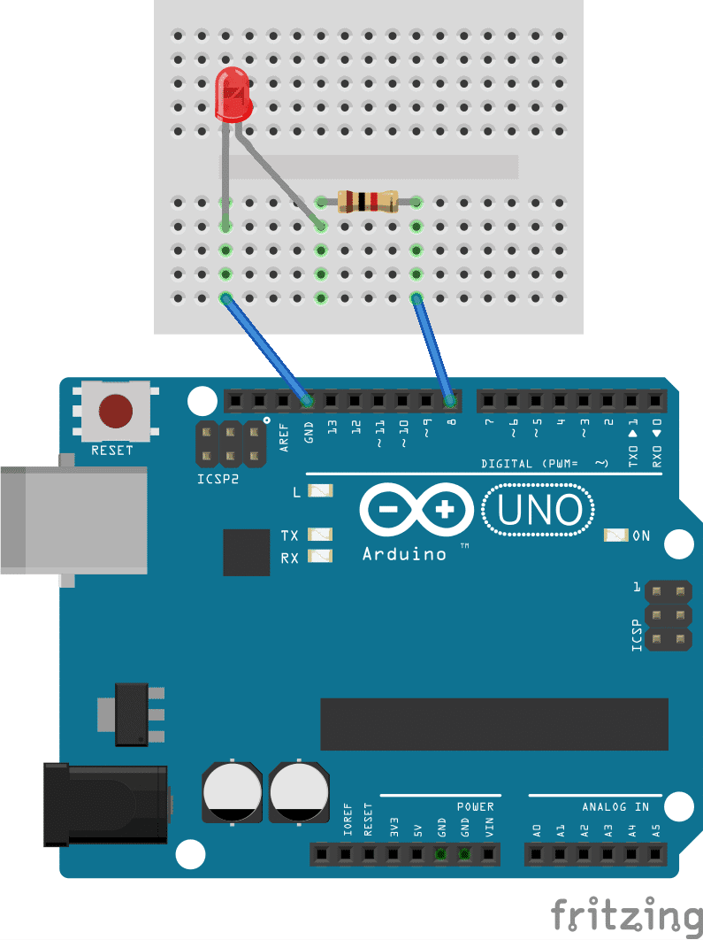
If you want to use a different pin to power the LED, it’s easy to change it. For example, say you want to use pin 8 instead of pin 13. First move the signal wire from pin 13 over to pin 8:
Now you’ll need to edit a line of code in the program so the Arduino knows which pins to use as output pins. That’s done on line 2 of the code above, where it says:
pinMode(13, OUTPUT);
To use pin 8, you just have to change the 13 to an 8:
pinMode(8, OUTPUT);
Next you’ll need to change the code that tells the Arduino which pins will get the HIGH and LOW output signals. That’s done everywhere there’s a digitalWrite() function. In the program above, there’s one on line 5 and one on line 7:
digitalWrite(13, HIGH);
digitalWrite(13, LOW);
To specify that pin 8 should get the HIGH and LOW signals, you just need to change the 13’s to 8’s:
digitalWrite(8, HIGH);
digitalWrite(8, LOW);
The finished program should look like this:
void setup() {
  pinMode(8, OUTPUT);
}
void loop() {
  digitalWrite(8, HIGH);
  delay(1000);
  digitalWrite(8, LOW);
  delay(1000);
}
After uploading, the LED should flash just like it did when it was connected to pin 13.
Controlling Multiple LEDs Together
You can control as many LEDs as you want as long as you have enough pins available. Let’s make the external LED flash along side the on-board LED to demonstrate. All we need to do is duplicate the code for pin 8, and change the pin numbers to pin 13.
Here’s an example of that:
void setup() {
  pinMode(8, OUTPUT);
  pinMode(13, OUTPUT);
}
void loop() {
  digitalWrite(8, HIGH);
  delay(1000);
  digitalWrite(13, HIGH);
  delay(1000);
  digitalWrite(8, LOW);
  delay(1000);
  digitalWrite(13, LOW);
  delay(1000);
}
You should be able to see both LEDs blinking. But they won’t be blinking in sync, they’ll be alternating.
The Arduino executes the instructions in the code from top to bottom. It reads each line and performs the task before moving onto the next line. Once it has read through to the end, it loops back to line 6 and starts over again.
In the program above, the code is executed in this order:
- HIGH signal sent to pin 8
- Wait for 1000 ms
- HIGH signal sent to pin 13
- Wait for 1000 ms
- LOW signal sent to pin 8
- Wait for 1000 ms
- LOW signal sent to pin 13
- Wait for 1000 ms
- Return to step 1
To get both LEDs blinking at the same time, we need to remove the delay between the HIGH and LOW signals of each pin, as shown in this program:
void setup() {
  pinMode(8, OUTPUT);
  pinMode(13, OUTPUT);
}
void loop() {
  digitalWrite(8, HIGH);
  digitalWrite(13, HIGH);
  delay(1000);
  digitalWrite(8, LOW);
  digitalWrite(13, LOW);
  delay(1000);
}
Now both LEDs should turn on and off at the same time. The tasks are executed in this order:
- HIGH signal sent to pin 8
- HIGH signal sent to pin 13
- Wait for 1000 ms
- LOW signal sent to pin 8
- LOW signal sent to pin 13
- Wait for 1000 ms
- Return to step 1
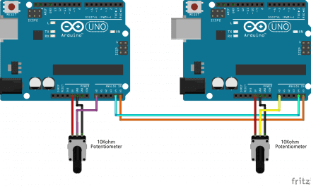
Now that you’ve seen how to control LEDs with the Arduino, check out part 2 of this series, where I’ll show you how to use a light dependent resistor to control how fast the LED flashes and how to control the pitch of sound output by a speaker.
If you have any questions or have trouble getting this project to work, just leave a comment below and I’ll try help you get it going. And be sure to subscribe! We send out an email each time we publish a new tutorial…


I am quite new at arduino. I have a arduino uno board. When I connect it to my computer and upload the code at the under the page it says:
“Cannot run program “{runtime.tools.avr-gcc.path}\bin\avr-g++” (in directory “.”): CreateProcess error=2, System cannot find the file.”
Whats I am doin wrong?
make sure you’ve selected the correct board and port under “tools.” it should be “arduino uno” and “usb” respectively.
hi
first disconnect your arduino and verifi the code.
then go to the tools menu and go to ports it will show a unique port for arduino select that and upload the coad
it will get uploaded
even i got the same problem i did this and it got solved..
You mean on/off state?
Easy and straightforward yes, but would it not be better practice to teach new users not to use ‘del… https://t.co/wMlEyX5YCx
curious to see if the code for this could be fed by way of an xml file or something, to control when the light is on and off.
please , how can I change the power of led ( I want to change its power highest or lowest while the led is on )
without using a manual method .
I want automatic way for this .
by programming .
I guess you need to deal with “analog pins” of Arduino.
If you copy paste the code into arduino ide it refuses to work. Why is there not a program that simply lets you do what you want in a sensible way? Let met just set the pin I want as an led and let me tell it what to do. I really feel like I threw money away with this.
Bro what error do you get on the IDE?
I haven’t been trying to pass the class that uses this on Coursera. I don’t even know about that.
Have you checked out the Tinker sight. I did some nice models on my table tonight with that.
Don’t listen to Mr. Perhaps. You need to understand that the internal LED on the Arduino Uno is on pin 13 on the digital side as shown in the article, also you need to make sure you include (using the include function) all the right packages to run this Arduino code. The code is there, circuit basics did it for you because you want to play pubg and not read the datasheet, but you’ve gotta make sure you include the right packages in the C program.
Hi. How can i use alot of leds using a breadboard and considering them as one big led connect it with just a single pin of the breadboard for the output? and power it with an external source?
Is there a way to make a light flicker on then off during a note? For reference, one of my lines of code goes like this:
digitalWrite(6,LOW);
digitalWrite(5,HIGH);
digitalWrite(5,LOW);
Serial.print(“ne, “);
tone(9, NOTE_B4); delay(1400);
I’m trying to get pin 5 to flicker on during the note, then turn off while it’s still playing. The issue is that the pin 5 LED doesn’t light up at all, and I can’t get it to work. Please help.
david
hello , i want to blinking led with 2hz 3hz 4hz 5hz 25hz 40hz with arduino uno but what is delay and calculation ?