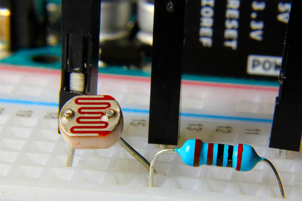
Whether you’re building a robot or configuring a monitor, begin your project by noticing the ambient light in your workspace. This reading may lead you to adjust the brightness of a clock or other display, or even set up an automatic nightlight that senses a darkening room. Light-dependent resistors (LDRs) are the key to building automated lighting. LDRs are useful and inexpensive, making them an excellent choice if you’d like to experiment without breaking the bank. We’ll pair an LDR with an Arduino Uno to demonstrate how they operate together.

Quick LDR Input Demo
First, here’s a quick demonstration of how to use an LDR:
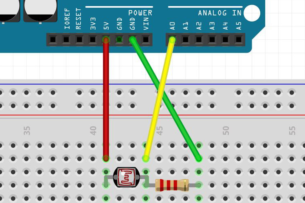
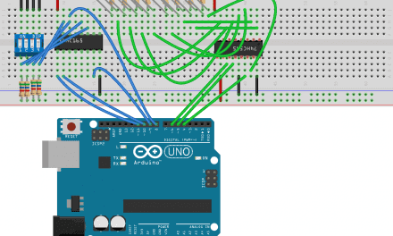
- Hook up the circuit shown in the above diagram using an Arduino Uno (or adapt it to any dev board with an analog input). The fixed resistor used here is two kilohms, but higher or lower resistors may work better in your situation.
- Once you complete the circuit, open Examples > Basics > AnalogReadSerial in the Arduino IDE, and load it onto your Uno.
- When you open the serial monitor up at 9600 baud, and you’ll see a steady stream of numbers from 0 to 1023 (indicating a voltage value of 0-5V scaled to a range of 0-1023) flowing down your console window.
What’s Happening Here?
You may wonder why you’re unable to hook the LDR straight from the +5V pin to the A0 pin. While the LDR’s resistance does change, you don’t have a voltage divider in this setup. Whether resistance is relatively high or low, it’s all “seen” across the LDR component, fixing A0 at +5V. When you add the resistor to ground, it forms a voltage divider. Now the LDR must “spread” the voltage across the two resistors in series, and A0 senses the middle value.
The equation at work here is:

To see what happens without a voltage divider, pull the ground pin out of the circuit board temporarily. You’ll see the serial monitor number jump up to 1023, indicating that the full 5V of potential is set at that pin.
Adjust LED Brightness Based on LDR Data
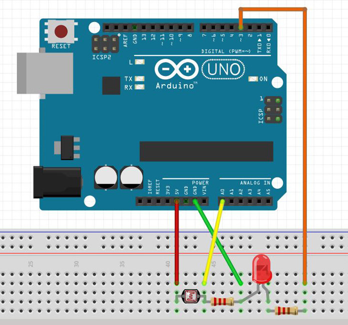
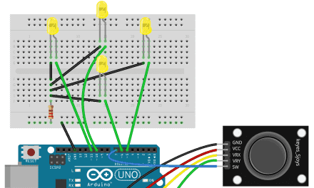
The resistor on the left is 2K ohms, and the resistor on the right is 220 ohms.
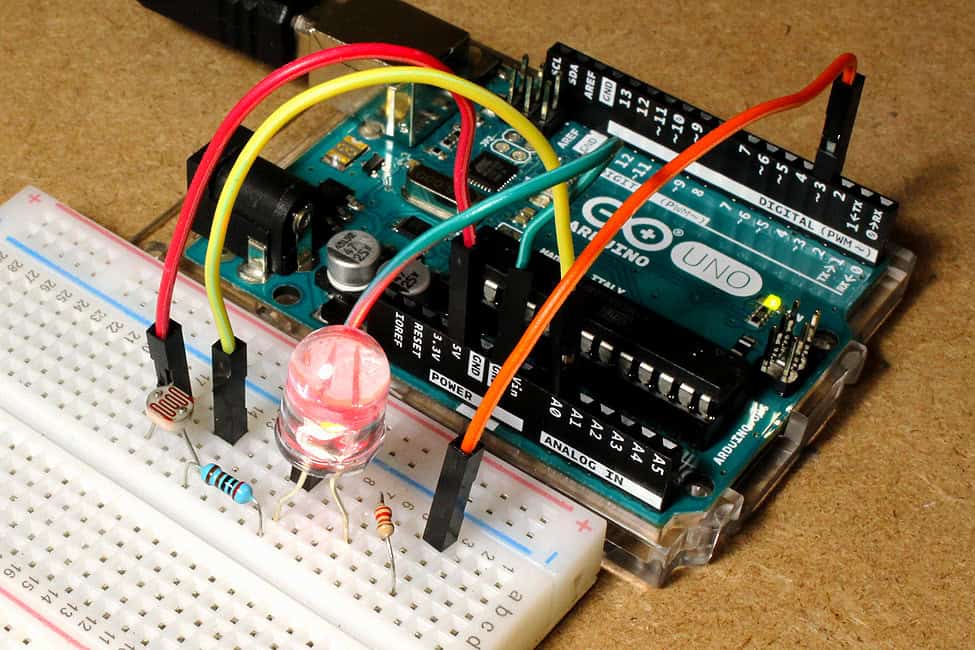
The easiest way to measure voltage is to use a multimeter. The magic of the Arduino is that you can program it to react automatically to changing conditions. For example, your Arduino can adjust the intensity of an LED in response to the ambient light detected by a LDR. You can build this device in a few steps:
- Add an LED and current limiting resistor are shown in the diagram above. Add a 220 ohm resistor to limit the current output:
- Check its functionality with the Examples > Basics > Blink example sketch, changing
LED_BUILTINto 3 in the three places where the light flashes. - You can change the perceived intensity of the LED by pulsing the LED very quickly and changing how long it stays on each time it flashes—a technique called pulse-width modulation, or PWM.
After connecting the LDR and LED to your Arduino, upload this code:
//takes input from an LDR or other analog input
//turns it into a PWM output for LED
//by Jeremy S. Cook

int ledPin = 3; //LED connected to digital pin 3
int PWMValue; //Sets PWMValue as integer

void setup() {
  Serial.begin(9600);
}

void loop() {
  int sensorValue = analogRead(A0); //reads the input on analog pin A0
  PWMValue = map(sensorValue, 0, 1023, 0, 255); //maps sensor value to proportional PWM values
  Serial.println(PWMValue); //print PWMValue (0 to 255) to serial
  analogWrite(ledPin, PWMValue); //writes PWMValue to digital pin 3
  delay(500); //delay helps one see change, could be omitted
}
The sketch above is a combination of the AnalogReadSerial example sketch used earlier, and another example sketch called Fading, located in the Analog drop-down menu. The code uses the “map” function to tie things together, scaling the 0-1023 LDR sensor input value to 0-255 for PWM output.
Depending on the amount of light that the LDR sees (and thus the voltage at A0) the LED will brighten or dim as needed. Pairing the LDR with an Arduino Uno helps make sure your LED doesn’t shine too brightly for its environment. This application is just one example of how to use these versatile sensors in your project.


Very good article, I now understand the need for the resistor in the circuit.