One of the most useful things you can do with an Arduino is control higher voltage (120-240V) devices like fans, lights, heaters, and other household appliances. Since the Arduino operates at 5V it can’t control these higher voltage devices directly, but you can use a 5V relay to switch the 120-240V current and use the Arduino to control the relay.

The Arduino can be programmed to turn on the relay when a certain event occurs, for example when the temperature of a thermistor gets higher than 30°C. Or when the resistance of a photoresistor drops below 400 Ohms. Almost any sensor can be used to trigger the relay to turn on or off. The trigger doesn’t even need to be from a sensor. It can occur at set time intervals, it can be triggered from the press of a button, or even when you get an email.
I’ll be using the SRD-05VDC-SL-C 5V relay in this tutorial because it’s very popular among Arduino and DIY electronics hobbyists. Let’s start with seeing how the 5V relay works, then I’ll show you how to set it up on the Arduino and give you some code to get it working.
Here’s the datasheet:
How the 5V Relay Works
The SRD-05VDC-SL-C relay has three high voltage terminals (NC, C, and NO) which connect to the device you want to control. The other side has three low voltage pins (Ground, Vcc, and Signal) which connect to the Arduino.
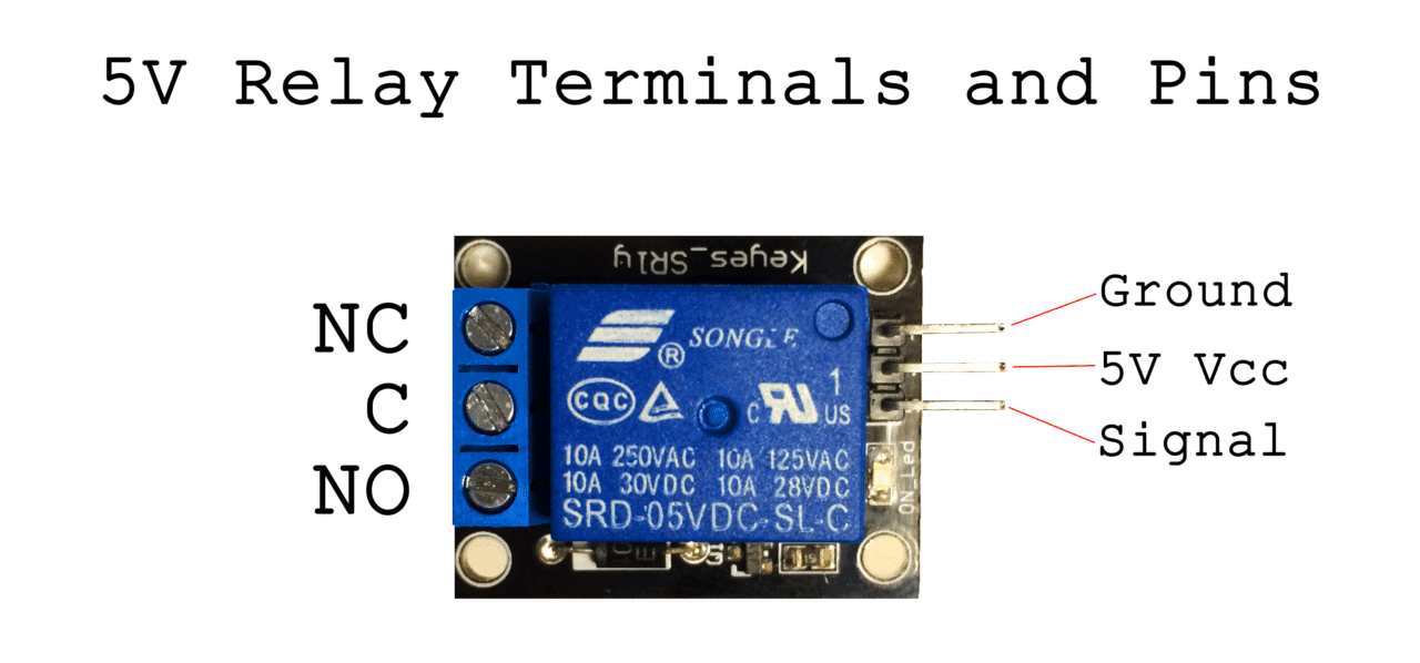
- NC: Normally closed 120-240V terminal
- NO: Normally open 120-240V terminal
- C: Common terminal
- Ground: Connects to the ground pin on the Arduino
- 5V Vcc: Connects the Arduino’s 5V pin
- Signal: Carries the trigger signal from the Arduino that activates the relay
Inside the relay is a 120-240V switch that’s connected to an electromagnet. When the relay receives a HIGH signal at the signal pin, the electromagnet becomes charged and moves the contacts of the switch open or closed.
Normally Open vs. Normally Closed
The relay has two different types of electrical contacts inside – normally open (NO) and normally closed (NC). The one you use will depend on whether you want the 5V signal to turn the switch on or turn the switch off. The 120-240V supply current enters the relay at the common (C) terminal in both configurations. To use the normally open contacts, use the NO terminal. To use the normally closed contacts, use the NC terminal.
Normally Open
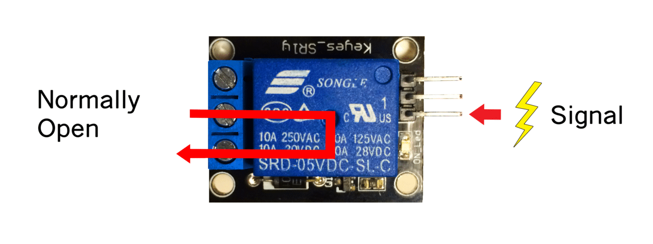
In the normally open configuration, when the relay receives a HIGH signal the 120-240V switch closes and allows current to flow from the C terminal to the NO terminal. A LOW signal deactivates the relay and stops the current. So if you want the HIGH signal to turn ON the relay, use the normally open terminal:
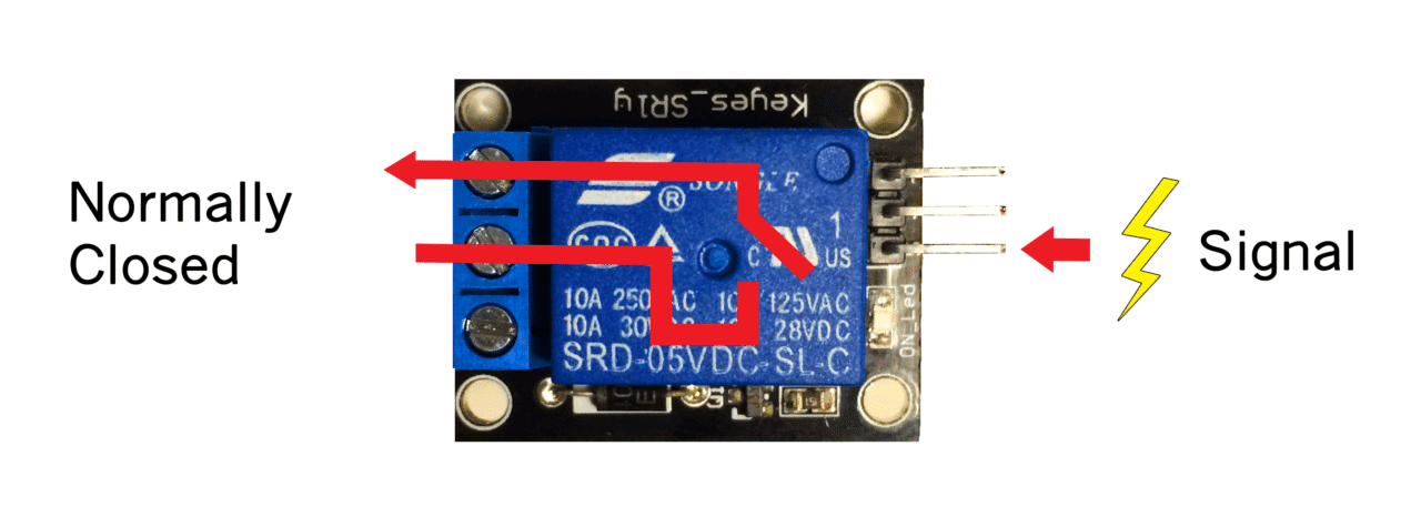
Normally Closed
In the normally closed configuration, a HIGH signal opens the switch and interrupts the 120-240V current. A LOW signal closes the switch and allows current to flow from the C terminal to the NC terminal. Therefore, if you want the HIGH signal to turn OFF the 120-240V current, use the normally closed terminal:
A Temperature Controlled Relay Circuit
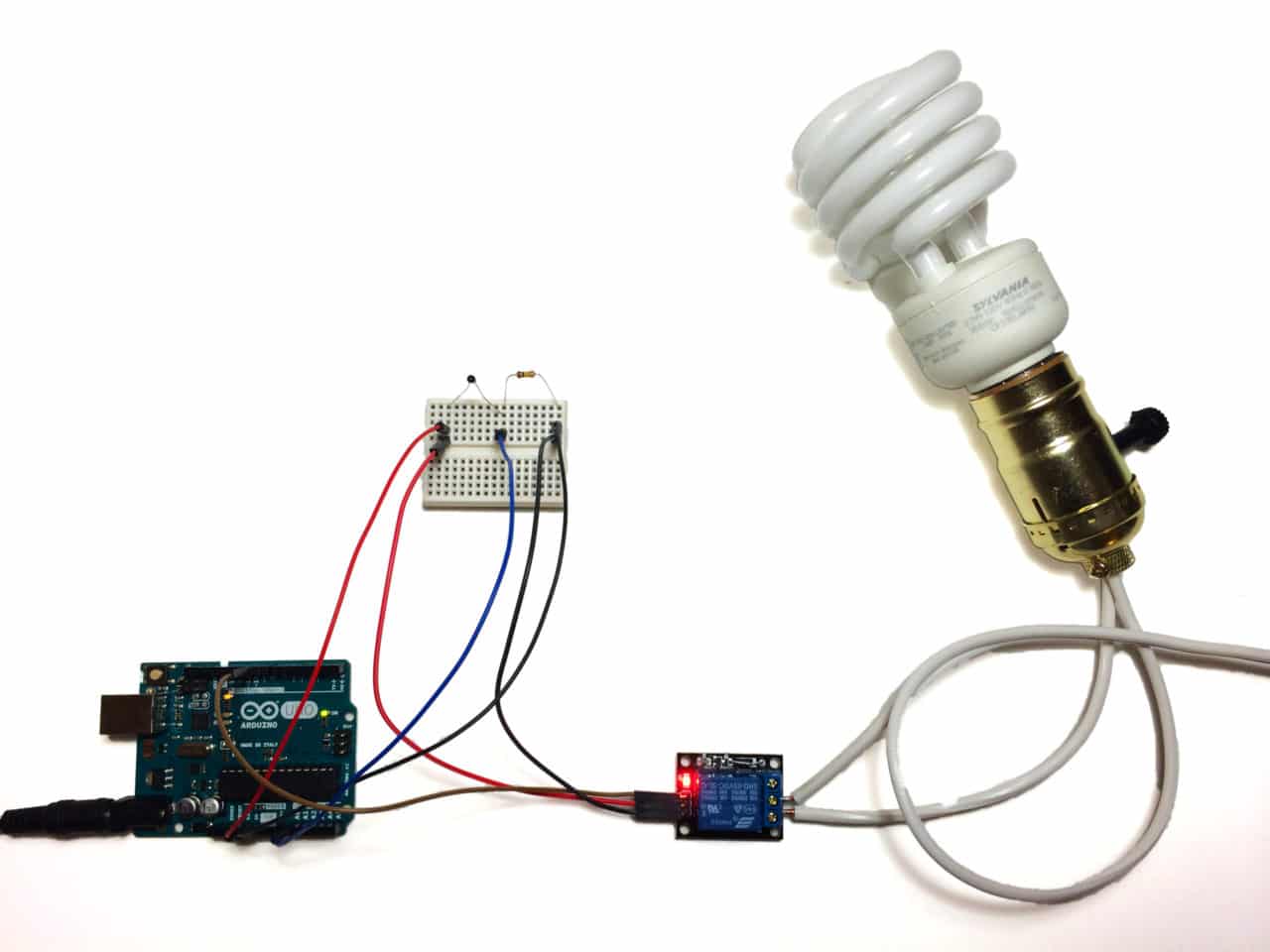
To show you how to wire the relay, let’s build a temperature controlled relay circuit that will turn off a light bulb when the temperature of a thermistor reaches 150°F. Thermistors are really useful with 5V relays. You can use them to turn off a large motor if gets too hot or turn on a heater if the temperature gets too cold.
WARNING – THIS PROJECT INVOLVES HIGH VOLTAGES THAT CAN CAUSE SERIOUS INJURY OR DEATH. PLEASE TAKE ALL NECESSARY PRECAUTIONS, AND TURN OFF ALL POWER TO A CIRCUIT BEFORE WORKING ON IT.
The setup is fairly simple, just make sure that the high voltage connections to the relay are secure:
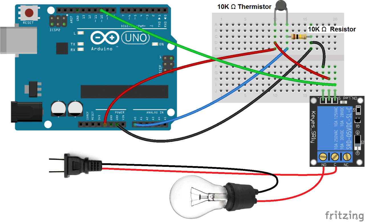
Identify the hot power wire (red wire in the diagram above) in the cord leading to the light bulb and make a cut. Connect the side leading to the light bulb to the NO terminal of the relay, and the side leading to the plug to the C terminal. This way the relay is on the hot side, and current is switched before it reaches the light bulb. It’s dangerous to put the relay on the neutral wire, since if the device fails current can still fault to ground when the relay is off.
The thermistor part of the circuit is set up as a voltage divider. The value of the resistor should be the same order of magnitude as the thermistor. For example, I’m using a 10K Ω thermistor, so the resistor should be 10K Ω as well. If you use a 100K Ω thermistor, use a 100K Ω resistor.
If you do use a 100K Ω thermistor, you’ll need to change line 7 in the code below to Temp = log(100000.0*((1024.0/RawADC-1)));. See our article on Making an Arduino Temperature Sensor for more information.
The Code
After everything is connected, upload this code to the Arduino:
#include <math.h>

int pinOut = 10;

double Thermistor(int RawADC) {
 double Temp;
 Temp = log(10000.0*((1024.0/RawADC-1)));
 Temp = 1 / (0.001129148 + (0.000234125 + (0.0000000876741 * Temp * Temp ))* Temp );
 Temp = Temp - 273.15;
 Temp = (Temp * 9.0)/ 5.0 + 32.0;
 return Temp;
}

void setup() {
  Serial.begin(9600);
  pinMode(10, OUTPUT);
}

void loop() {
  int val;
  double temp;
  val=analogRead(0);
  temp=Thermistor(val);
  Serial.print("Temperature = ");
  Serial.print(temp);
  Serial.println(" F");
  if (temp >= 150){
    digitalWrite(pinOut, LOW);
  }
  else {
    digitalWrite(pinOut, HIGH);
  }
  delay(500);
}
In this example, the relay will stay activated and let current flow through the light bulb until the temperature of the thermistor reaches 150°F. At 150°F the relay shuts off and the current stops. You can change the temperature in line 27 where it says if (temp >= 150){.
Here’s a video you can watch of me wiring up the relay to see it in action:
Another really useful project is a relay controlled power outlet box. This will let you plug any appliance into the outlet and control it with your Arduino without cutting into any power cords. You can also control several devices at the same time. See our tutorial “Turn Any Appliance into a Smart Device with an Arduino Controlled Power Outlet” to see how we built it.
Hope this is useful for you! Leave a comment if you have any questions. If you want us to let you know when we publish more tutorials, be sure to subscribe and share it if you know someone that would find it helpful. Thanks!


Sir, How can i display the temperature on LCD and serial monitor at the same time?
Check out our article on LCD displays for the Arduino, it should explain what you need to do that:
https://www.circuitbasics.com/how-to-set-up-an-lcd-display-on-an-arduino/
Where did you purchase this relay? I can’t seem to find it. I’ve found similar ones, but not this one.
I got it from Amazon, here’s a link to it
that relay really should be in a box. Mains nips are painful & dangerous.
That’s very true! You might want to check out this other article I wrote about how to make a relay controlled power outlet box: https://www.circuitbasics.com/build-an-arduino-controlled-power-outlet/
Hi there awesome video!! I was wondering how i can do this project with a light fixture that just has a hot wire and a neutral wire?
Mario:
If you see the diagram, the black wire between the plug and the light fixture is the neutral wire.
So in this case, like in yours, the light fixture just has a hot wire and a neutral wire.
So this project is EXACTLY what you are looking for.
:-)
The relay is UR (UL Recognized) but I would love to see the bottom of the PCB to verify proper creepage distances.
Thanks for sharing! You’re now featured on https://t.co/6mLwylPTZg
@iotcentrum
What is the value of Resistor and capacitor which is connected in bread board, It must required?
The black thing that looks like a ceramic disc capacitor is actually the thermistor. This is a voltage divider circuit, so the value of the resistor should be of the same magnitude as the resistance of your thermistor. For example, if you have a 100K Ohm thermistor, the resistor should be 100K Ohms also. Thanks for bringing that up, I will update the post…
Very nice, clear explanation.
Thank you.
How would I attach more than 1 relay (say 3) to control several loads individually?
is this sketch also for degrees C, instead of F??
It’s for Fahrenheit, but comment out line 10 to get Celsius…
Not today, but really soon! Thanks…
Thumbs up for sharing that tweet. It’s now live on my @RebelMouse! https://t.co/VZh00FocVe https://t.co/6mLwylPTZg
Love to see a tutorial using a MOSFET in place of the relay for voltages higher than 5V.
Would it be right to assume that if this approach is used on a 240V circuit that it can only interrupt one of the two phases, and that as a result the second phase will remain “hot” (and potentially lethal) at the load, even when it’s “off”?
If so, the modification to use the same idea with a 240V circuit would be to use a DPDT (double-pole/double-throw) relay instead: the poles being used for the two 240V hots and the throws being normally-open (NO) and normally-close (NC).
At least that’s what I’m setting out to try.
Thank you for the most excellent pictures.
And your photos were very helpful too. ;^)
Possibly like this Fujitsu FTR-F1.
http://electronicsure.ondatasheet.com/FTR-F1.pdf
can you explain more about the thermistor and the program written for it in the sketch?
Check out our other article on thermistors and the Arduino, I go a lot more in depth into the program and set up of the thermistor: https://www.circuitbasics.com/arduino-thermistor-temperature-sensor-tutorial/
will this still work even when i used the thermistor which is above 100k for recording high temperatures of around 200 celcius and 300 celcius for a 3d printer head
and what is power rating of a 10k resistor
Yes it will work for any size thermistor… You just want the resistor in the voltage divider be around the same resistance as your thermistor. Then you have to change line 7 in the code to the resistance value. So if you use a 200K thermistor, line 7 would be:
Temp = log(200000.0*((1024.0/RawADC-1)));
You say, just under the image, to “Connect the power wire of the light bulb cord to the NO (normally open) terminal of the relay, and connect the neutral power wire of the cord to the C (common) terminal of the relay.”
The image show the power wire is cut and the cut ends are then connected to the relay common and NO intact. Connecting power to neutral should blow a fuse when the relay closes the contacts!
Cheers,
Norm.
Sorry, can’t spell.
Contact, not intact. I hate auto correct sometimes!
Cheers,
Norm.
Sorry, that was an error… Thanks for commenting about it, I just changed the post.
Great tutorial! If you want to save a few bucks and just buy the relay itself, http://www.breakoutbros.com/using-a-relay-tutorial/ is a great tutorial on how to properly size your components around the relay.
Nice, thanks
And that capacitor between the vcc and gnd is for? decoupling?
I think the capacitor you’re talking about is actually a thermistor.
How about using dust sensor ?
I just used a thermistor because it’s a simple example, but any sensor that can be connected to the Arduino will work. It’s just a matter of writing the code that will take the input from the sensor and using it to produce a HIGH signal at one of the Arduino’s pins.
Can I use this relay to just make a connection without transferring power, like a makeshift momentary switch?
I need to control the relay using a serial monitor commands, is that possible? And how to do it , Thanks
Yes you can
Sir, if i’m using with DHT11and i want to use it for humidity, what should i change in the coding?
Check out the code at the bottom of this post: https://www.circuitbasics.com/build-an-arduino-controlled-power-outlet/
I’ve built the relay into a power outlet box, but the code takes the humidity reading from a DHT11 and uses it to control the relay.
any pointers on controlling power to ac devices? So say varying heat output of a hairdryer for example?
Hi I was just wondering if this relay would also work for outputting lower voltages, I am trying to use a push button to activate a relay from my 5v pin on the arduino uno with the output attached to a 6v power wheels motor ( the current is too high for me to want that involved with anything on my arduino). I saw the voltage rating for this is 120v, but was wondering if it will work for such a lesser voltage
Relay is an electromechanical switch and as such “doesn’t care” about the voltage going through – use it freely.
With high powers /high voltages it is useful because it totally separates both circuits (safety concerns). For lower powers /lower voltages you can also use a FET (“sort of” transistor) as a switch – it is much more simple. Switching a FET / transistor with arduino “out” pins is well documented.
*For the sake of accuracy: you can also switch bigger loads with transistors / FETs … Relay is a kind of obsolete tech really.
Not obsolete at all. A relay has the advantages mentioned in your post, namely a very large usable voltage range (from zero up to the maximum rated), AC or DC (either polarity), and very good physical isolation.
The failure mode of an overstressed relay is a lot like a fuse and very unlikely to cause any other damage, unlike a solid state device which can connect the switched supply to the device. For a solid-state switch to have that level of protection an opto-isolator is required, and that creates limits on the power that can be switched.
The main advantage of solid state switches is faster operation and cleaner switching.
Hi
I have a question about the Songle relays. The spec sheet says the current draw is about 85mA. Can you tell me the current draw of the input pin only. I presume most of the current comes from Vcc.
Some basic remarks:
1) Relays: in DC-control-circuits should have a flyback diode connected in parallel to the coil of the relay (eg 1N4001 – but check the relay data sheet for choosing the right diode). Since an inductor (the relay coil) cannot change it’s current instantly, the flyback diode provides a path for the current when the coil is switched off. Otherwise a large voltage spike will occur causing arcing on the switch contacts which will likely destroy the switching transistor, etc.
2) since an Arduino-PIN sources max 25mA, the relay cannot be switched directly from the Arduino-pin. Therefore eg a transistor (BC547 or 2N2222, etc) should be used (search in google for more details and sample circuits) for switching the relay.
3) Powering the Arduino by the means of the USB-connection (which provides appr 100mA) may be not enough to switch relays. Use a separate wall-plug with sufficient power (>500mA, better more).
4) If the relay should switch AC-loads, the use of an opt-isolator is recommended to separate the control-circuit from the switching-circuit (relay). Also the electrical paths for the AC-lines on the relay-module should be wide enough (min 3mm), as short as possible, separated from any other path on the PCB and not too close to each other.
This is useful to me.. this content have a useful information about basics of relays.
Mohammad Abdulhay this might be useful
Sir,
I want to create continuous fast pulses sent to the relay. Please advise on the code to use, and the circuit.
relays are electromechanical devices and as such VERY UNSUITABLE for “continuous fast pulses”. Use “solid state relay” assembly or transistor+optocoupler instead.
How did you draw the relay in Fritzing software? Please help me with this.
Hi. How cn i operate a complete home with adruino and relays… Imagine i have more than 50 Switches to operate in a complete home. Do i have to keep 50 Relays?
Would be grateful for a schematic of the circuit.
This post is inaccurate. Is misleading. Leads to overloading Arduino. Is dangerous.
– A relay is not the same thing as the “Relay module” you are using here. I came to this page looking how to hook up the relay (just the component, so this post doesn’t help me much). No relay (as a component) has a “signal” pin on the coil side, just two pins (which then need additional circuitry for load and spikes regulation). This is a big disinformation – try to change this.
– I have trouble understanding why did you have to complicate / and obfuscate this post with temp sensing – if the title is about using the relay (or relay module), make a decent post about it … i have spent 5 minute looking at the fritzing pic wandering what is the point of thermistor (it could be inrush current regulation, but then it wouldn’t be in circuit this way) – then I realized it is a part of some other bussiness
– it is a “circuit basics” page. I strongly advise not to post high voltage designs to such a page – look at the comments and questions in them if you think I am overreacting. Make the relay switch a high current / low voltage load if you want to make an instructable.
great! I’m making a circuit for an ice maker, but I have trouble finding the thermistor data sheet, and I saw that in your code you have the coefficient of the thermistor that you use, I want to know how I can get the data I have I just know it’s 10k and nothing else.
or with the formula of your code can I apply it to this thermistor?
I would appreciate your help,
This is the first time I have messed with a relay so I guess there are conventions involved; however, the fact the “C” stands for “common” seems dangerous. In household AC the neutral wire is also sometimes referred to as “common”. But in this circuit the hot wire is connected to “common”. Is this just a convention when dealing with relay’s I am not aware of?
I want to do something similar with a DHT 11, but i have a problem with this. If the temperature reaches the vale, and the lamp turns off, the temperature will also go lower, and that is going to make the lamp go on and off in aloop. How do I introduce a range, so it gets more stable?
Dears, i have a doubt.
You said that we have to identify the power wire! Suppose the three hole of my wall socket are: A – the hot power wire, T- the ground and B – the neutral wire.
I named the three pin of the plug A1, T1 and B1 ad connected A1 to C on the relay and B1 to the lamp.
If i insert the pin A1 to A and B1 to B in the wall socket the condition of your diagram is satisfied but i can insert the plug two wais. If i insert A1 to B and B1 to A then power wire goes direc to the lamp and the neutral to the relay.
This, probably, is a problem. How can it be solved?
Thanks in advance.
Can we control 12V DC circuit using the same 5V relay
Hello sir, I want to use the 5v relay but controlling it via the computer keyboard chip. when capslock is on the is 3v across it, so i wanted to use this voltage to control my 5v relay.
Schematic or references will be helpful….THANK YOU
Hi, on fritzing I can’t find the relay image like the one used by you, how did you insert it? where do you find it?
am working on a system to turn my room fan on if the temp reaches above a certain point. I figured out how to turn the relay on or off depending on temp, but it tries to turn the relay state on or off on every loop cycle. Is there a way to determine if the relay is currently in NO or NC position so I can have the loop cycle only change state if it is not in the correct position?
I’m trying to connect ldr with automatic light intensity change and I used the online code to interface and controll but the ldr was automatically on and off without intensity change and in dark time the led goes to off state and also dark in the automatically light goes to off reduce this please provide the correct solution to solve this problem thank you
Hi its very useful to us i tried to control the light using arduino uno with two channel relay board for automatic light ON & OFF system using LDR, i change my option this is very useful application for home applications Thanks a lot…
Hi,
I’m watching your videos on using Arduino and 5v relays…
I’m trying to figure out some simple code to get a temp reading from DarkSky and if the temp is below, 30, turn on the relay.
And when it goes back above 30, to turn the relay back off.
But, I’m a novice and can’t figure it out.
Can you help or suggest where to go for help?
I appreciate you explaining to make sure to secure the voltage connections and the relay. when setting it up. My son has a project for school, and he wants to make an electric car. I will be sure to get him the relays he needs and other parts to complete his project.
hi , is it possible to drive mosfet switch (h-bridge) using relay as an interface between arduino and h-bridge?
Sir, how did you get this specific relay into the Fritzing software
What if I link my stuff on NC but it’s turns on when HIGH and turns of when LOW ???
Thank you for your useful content
good
very very good
Thank you soooo much for this!!!! We tried every single thing and nothing worked, but this worked!!! Your circuit diagram helped us a lot!!d