So we’re down to part four of our tutorial series on wave generators and oscillators! Check out some of the previous articles in this series:

- How to Build a Square Wave Generator
- How to Build a Sawtooth and Triangle Wave Generator
- How to Build a Sine Wave Generator
And for this last one, we will look at crystal oscillators.
Crystal oscillators must surely be the most common of all electronic components. They are everywhere—on your phone, radio, TV, PC, laptop, microcontroller, and Arduino, to name a few. This is because they are unique in working at a single frequency—they are highly stable and drift-free. In this tutorial, we will look inside the can and see how crystal oscillators actually work.
How Crystal Oscillators Work
Crystal oscillators are loosely divided by the frequency they work at and whether they are fundamental oscillators—work at the frequency marked on the can or at even multiples of that (overtone oscillators).
Any oscillator needs only two things to work—positive feedback and some amplifier. The amplifier can be a transistor, FET, op-amp, or digital gate. The kind of amplifier you will need will depend on the frequency. Op-amps may work at low-frequency gates low to medium and transistors and FETs at any frequency, especially at the higher end.
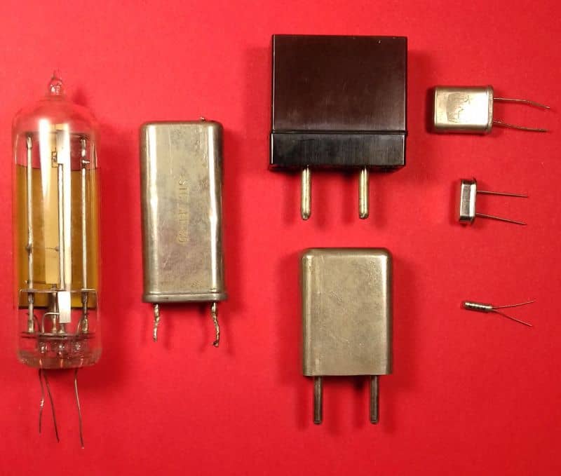
Not only do crystals come in many shapes and sizes, but they also come in different quartz cuts.
Let’s take a look inside a crystal oscillator:
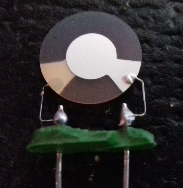
As you can see from the picture above, there are three main parts. The wire leads connect to two silvered plates on either side of the quartz slice which form a capacitor. Finally, the quartz itself will behave like an inductor (a large one) and a tiny capacitor in series:
For example, look at the equivalent circuit below:
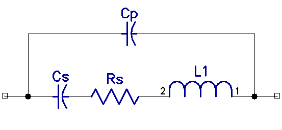
Rs is the resistance of the leads, Cp is the capacitance of the silvered plates, and L and Cs are hidden inside the quartz.
The property that makes the crystal so very stable at one frequency is its Q, and this is huge, typically 20 to 30 thousand. As Cp and Cs are very small, for L to resonate, it has to be huge, typically several Henries! Q is the ratio of reactance to resistance.
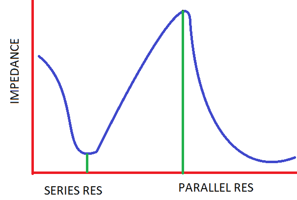
As you can see from the graph below, crystals have two resonant points. A lower impedance series resonance that is largely governed by Cs and L1, and a larger impedance parallel resonance that is largely governed by Cs in series with L1 and both in parallel with Cp.
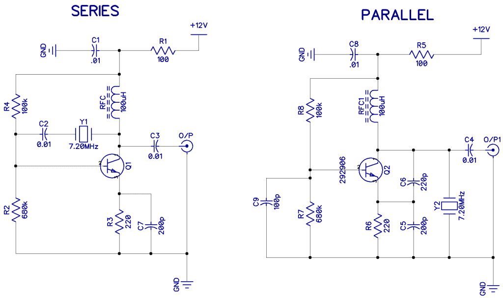
The two oscillator circuits below are suitable for using crystal oscillators in series or parallel mode:
Inverting Gate Oscillators
The simplest oscillator you can make is with one inverting gate like this:
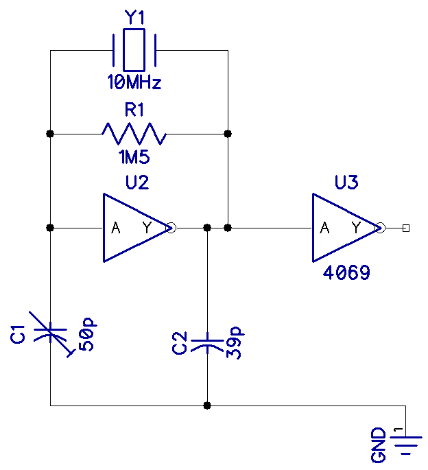
Almost any inverting gate CMOS will work here, including the 4069, 74HC04, 74HC14, etc.
Unintuitively, all digital gates have a gain, and if you bias them (like with the 1M5 resistor above), they work as amplifiers. The output only provides 180° of phase shift, so the capacitors are there to provide the rest of the phase shift to make the feedback positive (360°) and cause oscillation. None of these components are very critical. R1 can be anywhere from 10k to 10M, and C1 and C2 from 10p to 100p. It all depends on the frequency and the type of cut of the crystal. The values above are typical and work on my breadboard. I used a variable capacitor for C1 so that I could set the frequency to exactly 10.0000MHz on my counter. If you don’t need to be that precise, you could just use a second 39p capacitor.
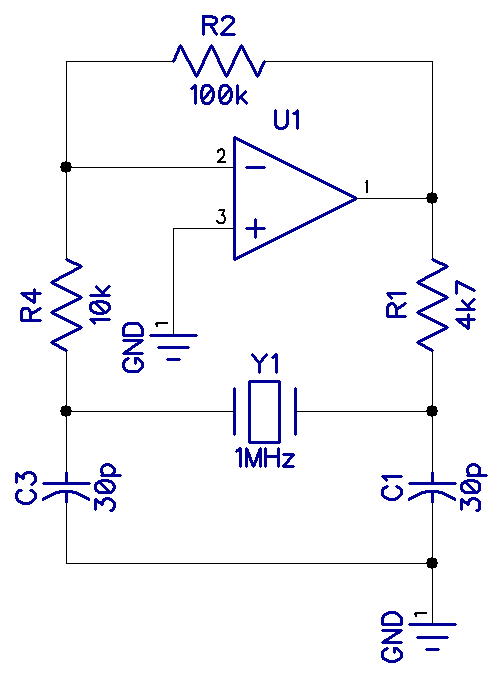
Crystal Oscillators and Op-Amps
Crystal oscillators can also be made with fast op-amps. Here, an LM318 op-amp is used. The output was not very clean, and there are better ways to make oscillators:
Radio Frequency Oscillators
Radio hams have relied on crystal oscillators such as the circuit below for decades. Many spy transmitters were made during WW2 with circuits such as the one below (using valves, of course):
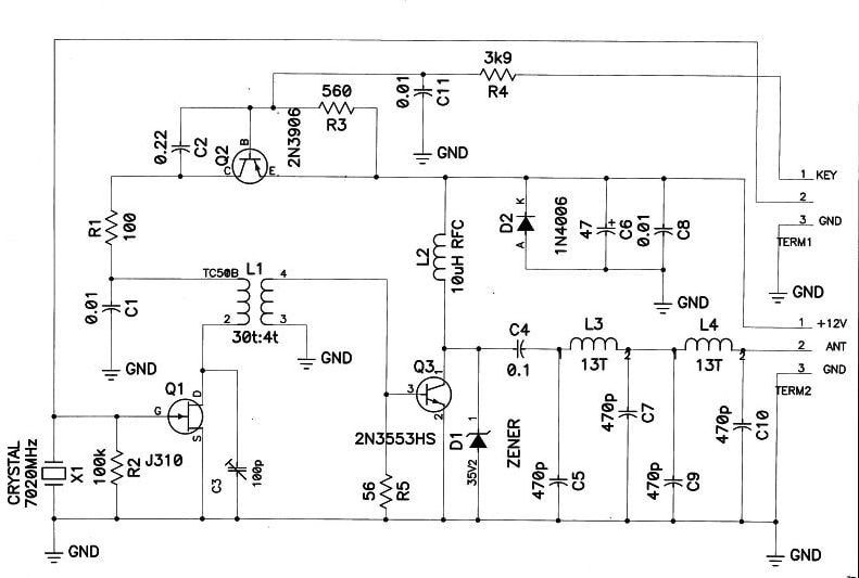
The main crystal oscillator is in the lower-left corner Q1, X1, etc., followed by a small 1W power amplifier (PA) Q3 driving a low pass filter and matching circuit. The oscillator is switched on and off through a key shaping circuit (Q2) to make it start and stop gently. This prevents clicks from being transmitted.
The FET oscillator’s drain circuit is a tuned circuit (L1 C3) to provide more power and a cleaner waveform. These all form an amateur band (40m) QRP CW (continuous wave or Morse code) transmitter.
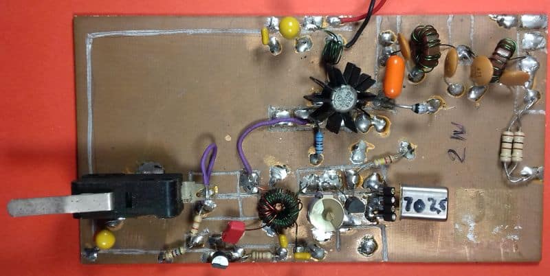
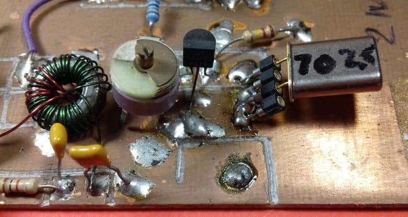
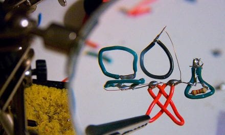
The completed prototype board is shown below with a detailed view of the crystal. Note that the Morse key is a micro switch.
Overtone Oscillator
Another useful crystal oscillator is the overtone oscillator shown in the schematic below. Standard-cut crystals are difficult to make; higher than 20MHz as the wafer of quartz becomes too thin. A solution to this is to use an overtone oscillator.
An example is the frequency source for a 144MH transmitter. The oscillator has a tuned load at an odd multiple of the fundamental frequency of the crystal. In fact, little or no part of the fundamental is present at the output. Although the circuit below will work with fundamental cut crystals, it is best to use overtone mode crystals for this application.
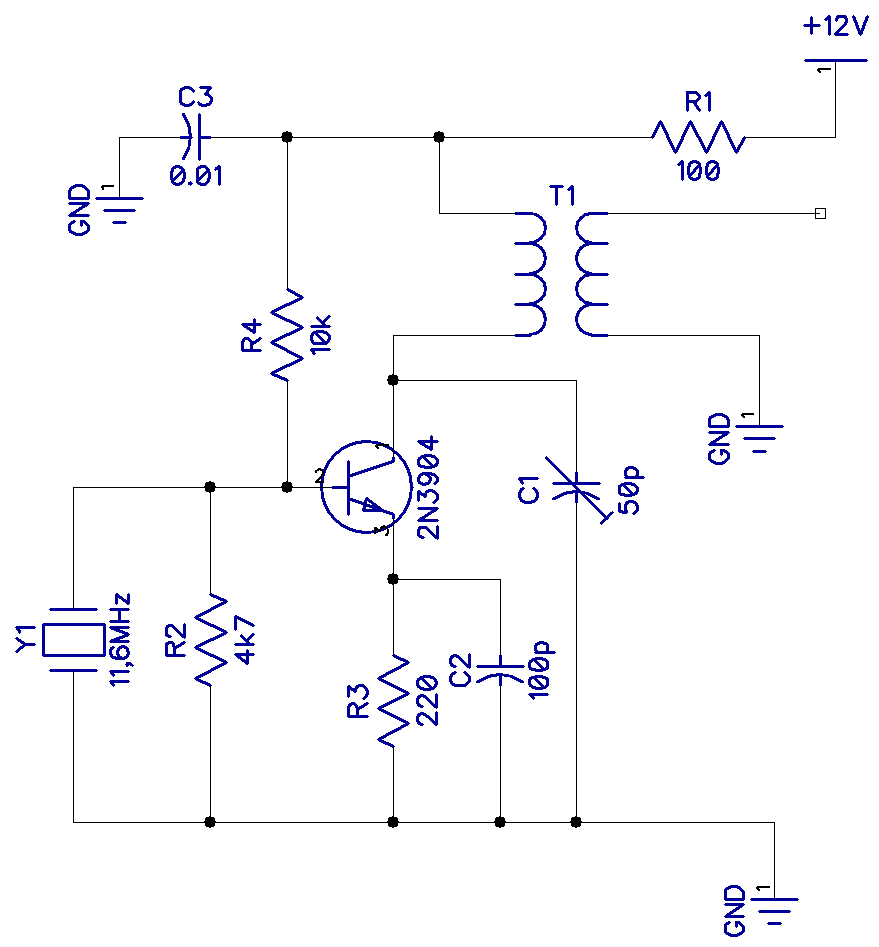
This oscillator has an 11.6MHz crystal and is tuned to the 3rd overtone or harmonic of 34.8MHz. The sine wave below is quite good, and there is almost nothing of the 11.6MHz fundamental in the 34MHz output in the Fourier display.
The output transformer is an Amidon T-50_6 type with 15 turns on the primary. The secondary turns will depend on what you connect it to.
If the output was followed by a tripler (3X) circuit, it would be the source for a 104MHz transceiver.
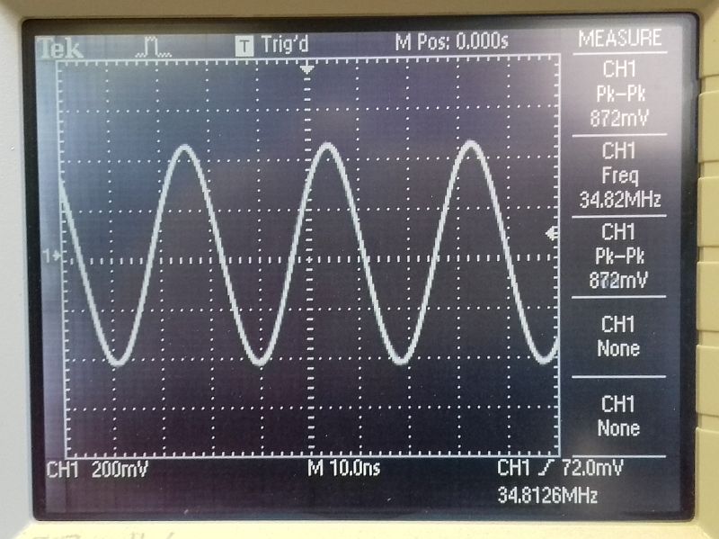 |  |
| 34MHz output of 11.6MHz overtone oscillator | 11.6MHz signal not visible |
This concludes the four-part series on oscillators! I hope you have learned as much from it as I have from researching and bread-boarding it!
Be sure to leave a comment below if you have questions about anything!


Congratulations for your work!!
I have learnt a lot and remembered other forgotten details. Please go on making more of these masterclasses.
Your explanations are clear and easy to follow.
Thanks.
Brilliant article. I have been looking for a detailed description of oscillator circuits. I have a couple of questions:
1. Do I need to select resistors and capacitors to suit the frequency of the oscillator crystal?
2. How much output current is provided and what can I drive with it?
3. How would you test the output without an oscilloscope?
Many thanks.