Gyroscopes measure the speed of rotation around one or more axes. Connected to the Arduino, they can be used to control the orientation of drones, robots, and autonomous vehicles, or to detect body motion with wearable sensors. The gyroscope we will use in this article is the L3GD20H 3-axis gyroscope. It’s probably the most popular gyroscope for Arduino projects.

Watch the video for this tutorial here:
Overview of the L3GD20H Gyroscope
This is the L3GD20H gyroscope:
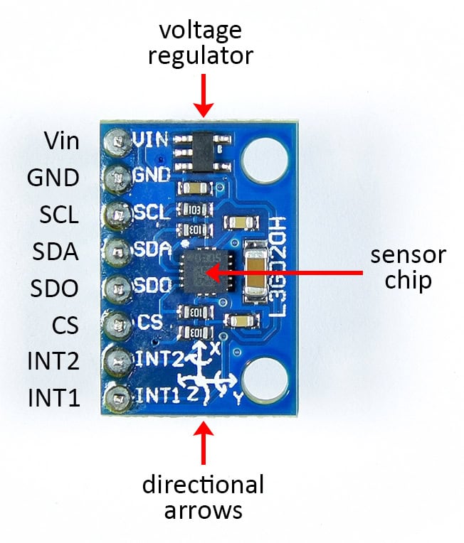
The L3GD20H sensor chip runs on 3.3 volts, but if the breakout board has a voltage regulator, it can be powered from the Arduino’s 5 volt power supply.
The gyroscope has eight pins:
- VIN: Power input. Normally 3.3 volts but can be 5 volts if there is a voltage regulator.
- GND: Connects to ground on the Arduino.
- SCL: For I2C communication.
- SDA: For I2C communication.
- SDO: For SPI communication.
- CS: For SPI communication.
- INT2: Hardware interrupt pin.
- INT1: Hardware interrupt pin.
Directional arrows are printed on top of the board to indicate how the sensor’s axes are oriented in relation to the PCB. The z axis points up and down 90° to the plane of the PCB.
How the L3GD20H Gyroscope Works
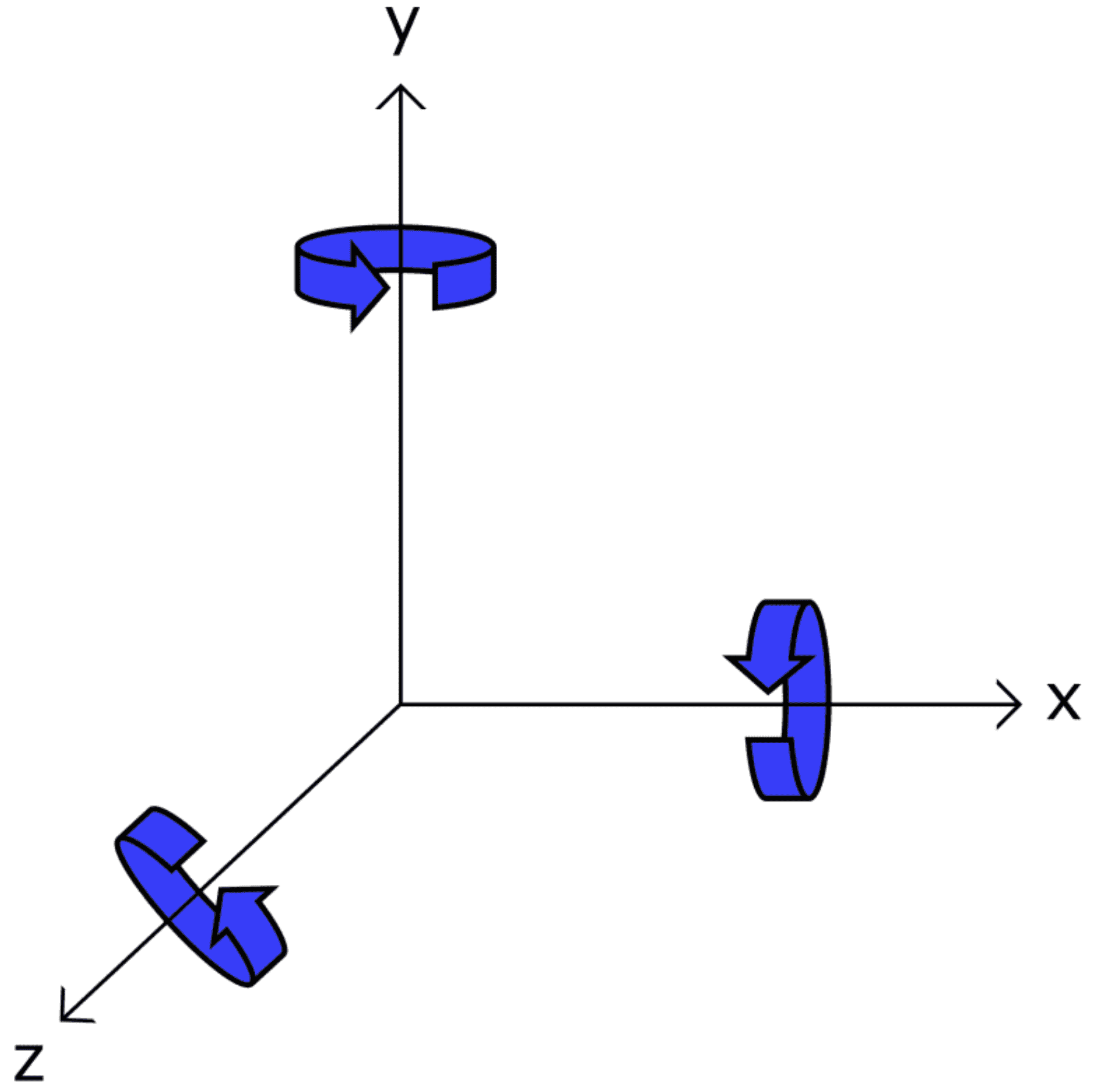
The L3GD20H measures rotational speed around its x, y, and z axes:
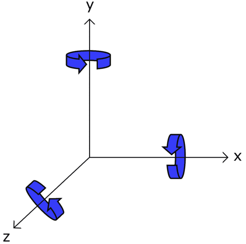
Here the y axis is shown as the vertical axis, the x axis points to the right, and z extends upwards out of the plane of your screen. The gyroscope outputs rotational speed values for each of these axes. The sensor’s raw output can be converted to degrees per second or radians per second.
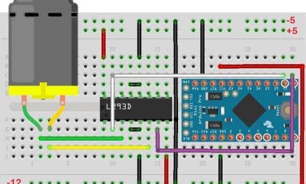
How to Connect the L3GD20H Gyroscope to the Arduino
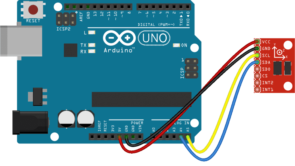
The L3GD20H can communicate with the Arduino over I2C or SPI. We will connect the sensor with I2C since it uses less wires.
Here are the parts you’ll need to build the project:
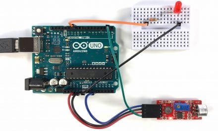
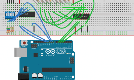
Follow the wiring diagram below to connect the gyroscope to the Arduino:
How to Program the L3GD20H on the Arduino
We will use a library called the L3G library from Pololu to program the gyroscope. You can download the library on GitHub from this link.
After the library is installed, upload the code below to the Arduino. This sketch will output the raw gyroscope readings to the serial monitor:
#include <Wire.h>
#include <L3G.h>

L3G gyro;

void setup() {
  Serial.begin(9600);
  Wire.begin();

  if (!gyro.init()) {
    Serial.println("Failed to autodetect gyro type!");
    while (1);
  }

  gyro.enableDefault();
}

void loop() {

  gyro.read();

  Serial.print("X: ");
  Serial.print(gyro.g.x);
  Serial.print(" Y: ");
  Serial.print(gyro.g.y);
  Serial.print(" Z: ");
  Serial.println(gyro.g.z);

  delay(200);
}
Explanation of the Code
The first thing we do is include the libraries. We’re using I2C, and anytime we use I2C we have to include the Wire library. We also need to include the L3G library. Next we create an object called gyro from the L3G class.
In the setup() section, we initialize the serial monitor and initialize the I2C protocol with Wire.begin(). Then we have an if statement with the init() function as a condition. The init() function detects the type of gyroscope connected to the Arduino, and its I2C address. If the gyroscope type is not detected, the init() function will return a false value. In that case, the NOT operator makes the condition true. When the condition is true, the body of the if statement is executed, which prints some text that says “Failed to autodetect gyro type”, followed by an empty while loop that continues on indefinitely.
If the gyroscope type is detected, the init() function returns a true value. But the NOT operator makes the condition false, so the program skips the if statement.
At the end of the setup() section, we use the enableDefault() function called through the gyro object. This turns on the gyroscope and sets it’s sensitivity range to ±245 degrees per second.
In the loop() section, we read the raw values of each sensor axis by calling the read() function through the gyro object. The sensor outputs a 16 bit value for each axis. The readings for each axis can be accessed using the following variables:
- X axis:
gyro.g.x - Y axis:
gyro.g.y - Z axis:
gyro.g.z
Using the variables above, we use a series of Serial.print() functions to print the raw sensor value of each axis to the serial monitor. These variables can also be used in other functions or equations.
At the end of the loop() section, we delay for 200 milliseconds to make the output easier to read.
Once the gyroscope is connected to the Arduino and the code is uploaded, open the serial monitor to see the raw data being output from the sensor:
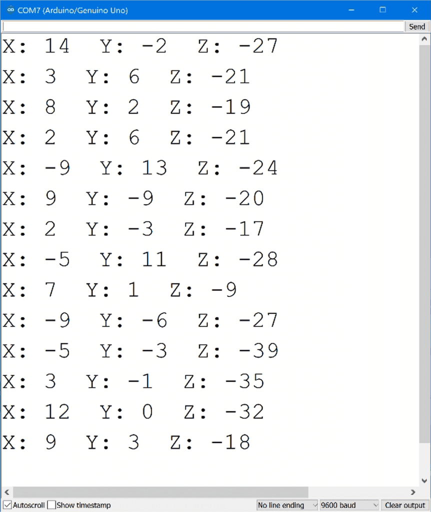
The numbers you see are the raw 16 bit values output from the sensor by default. Now let’s convert these raw values to something easier to work with.
How to Convert the Raw Values to Degrees Per Second and Radians
To convert the L3GD20H gyroscope’s raw values to degrees per second or radians, all we need to do is apply some conversion factors. The conversion factors can be found on page 10 of the L3GD20H datasheet. Look for the table with the sensor’s mechanical specifications. The “So” specification gives the conversion factor for each sensitivity range:
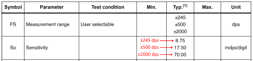
By default, the L3G library sets the sensitivity at ±245 degrees per second (dps). At this sensitivity, there are 8.75 milli-degrees per second, per raw digit.
This sketch will read the raw sensor output of each axis and convert it to degrees per second or radians per second:
#include <Wire.h>
#include <L3G.h>

L3G gyro;

void setup() {
  Serial.begin(9600);
  Wire.begin();

  if (!gyro.init()) {
    Serial.println("Failed to autodetect gyro type!");
    while (1);
  }

  gyro.enableDefault();
}

void loop() {

  gyro.read();

  float xDPS = (gyro.g.x * 8.75) / 1000;
  float yDPS = (gyro.g.y * 8.75) / 1000;
  float zDPS = (gyro.g.z * 8.75) / 1000;

  //float xRAD = xDPS * (3.14159 / 180);
  //float yRAD = yDPS * (3.14159 / 180);
  //float zRAD = zDPS * (3.14159 / 180);

  Serial.print("X: ");
  Serial.print(xDPS);
  Serial.print(" Y: ");
  Serial.print(yDPS);
  Serial.print(" Z: ");
  Serial.println(zDPS);

  delay(200);
}
Explanation of the Code
The top of the sketch and the setup() section are the same as the raw output sketch we saw earlier.
In the loop() section, we still need to get the sensor measurements for each axis with the read() function. Then we convert the raw measurements to degrees per second. To do that, we declare three separate float variables – xDPS, yDPS, and zDPS. Each variable is set equal to the raw output for each axis – gyro.g.x, gyro.g.y, and gyro.g.z. Then we multiply each raw output by the conversion factor 8.75 to convert the readings to milli-degrees per second. Then we divide by 1000 to convert milli-degrees per second to degrees per second.
To get the sensor readings in radians per second, just multiply the xDPS, yDPS, and zDPS variables by π/180°. Uncomment the xRAD, yRAD, and zRAD variable declarations in the sketch above to get the sensor readings in radians per second.
Next we print the converted gyroscope readings to the serial monitor with a few Serial.print() functions. This time we are printing the xDPS, yDPS, and zDPS variables that hold the gyroscope readings in degrees per second. To display the readings in radians per second, change the argument in each Serial.print() function to xRAD, yRAD, and zRAD.
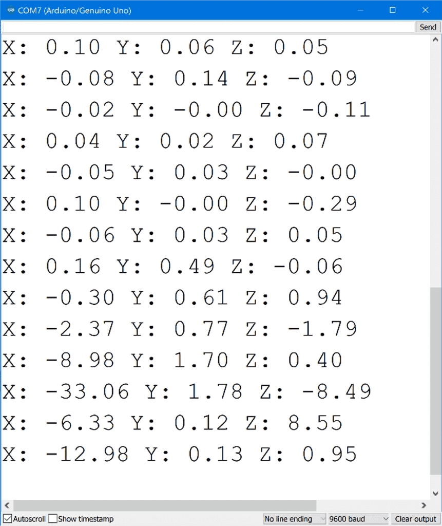
Once the sketch is uploaded, open the serial monitor and you should see the reading from each gyroscope axis in degrees per second:
Feel free to leave a comment if you have any questions or problems setting this up!


Hi. You seem to have Pi at 3.1459 rather than 3.14159 in your code.
Good eye! Thanks for the catch. The code has been updated.