In this article, we will first talk about radio frequencies and amplitude modulation. Then we will build three different AM radio receivers in order of increasing complexity. The first AM radio has no amplifier and only relies on resonance to create sound. The second AM receiver has a transistor amplifier, and the final AM receiver circuit uses an LM386 amplifier chip.

Introduction to AM Radio Receivers
Medium wave is a band of radio frequencies extending from 530kHz to 1700kHz. On the other hand, short wave extends beyond that and up to about 30MHz.
Medium wave and short wave were the main broadcast radio bands until the advent of FM. But they are still popular as they have more channel space than FM stations and offer longer range coverage, especially at night via the ionosphere. AM receivers are also simple and easy to build.
Radio stations in the medium wave and short wave bands transmit their signals using Amplitude Modulation (AM). This means that the transmitter radio (or carrier) signal is modulated with the music or speech content in a manner that the amplitude of the carrier is varied in relation to the incoming speech or music. AM is also used on all aircraft radios from 108 to 136MHz.
How to Build a Simple AM Radio
Shown below is a simple (and magical if you have ever built one) crystal radio circuit. Building this is an excellent start in understanding how AM radios work:
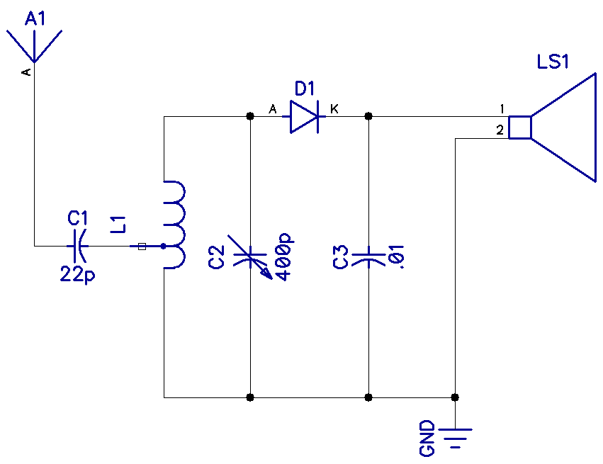
The diode is ideally a germanium diode, like the OA81, as it has a lower forward volt drop. But any diode will work, only with less volume. The LS is a high-impedance piezoelectric headphone like the vintage 2000Ω “crystal earpiece”.
Capacitor C2 is a variable capacitor of about 300pF to 500pF.
L1 is a coil wound on a ferrite rod with about 50 to 60 turns. The tap is at about 5 to 10 turns to be coupled to the antenna. Use magnet wire to wind the coil if possible.
For this radio work well, you will need a good earth connection and at least 20m of wire as high as possible outdoors as an antenna. What’s truly amazing here is that this circuit will work without any batteries and provide hours of AM listening fun.
How the AM Radio Circuit Works
When the reactance (AC resistance) of capacitor C2 is the same as the reactance of the coil L1, resonance occurs at the frequency f=1/2π√(LC).
For example, with L1 equal to 300 uH and C2 equal to 100 pF:
F = 1/2π√((0.0003 H)*(0.000000000001 F)) = 919kHz.
If they are in parallel (as in our circuit), the combined impedance is very high, and if they are in series, resonance also occurs but the combined impedance is very low. The ratio of this dynamic impedance to any loss resistance present is called Q. The greater the Q, the more selective the circuit becomes.
This increase in selectivity enables the circuit to tune into the station you want. If the selectivity is low, you would hear other neighboring stations at the same time. (C1 is a small capacitor as well as the tap to prevent the antenna from damping the Q of the tuned circuit).
The diode D1 rectifies and recovers the modulation and the capacitor C3 bypasses the radio (RF) part-leaving the original modulated audio. By changing the capacitance of C2 (the resonant point), the tuning can be varied across the medium wave band.
Transistor Amplified AM Radio
Before the advent of easy-to-use amplifier IC’s such as the LM386, receivers were made from designs using discreet components. A popular choice was the regenerative receiver shown below.
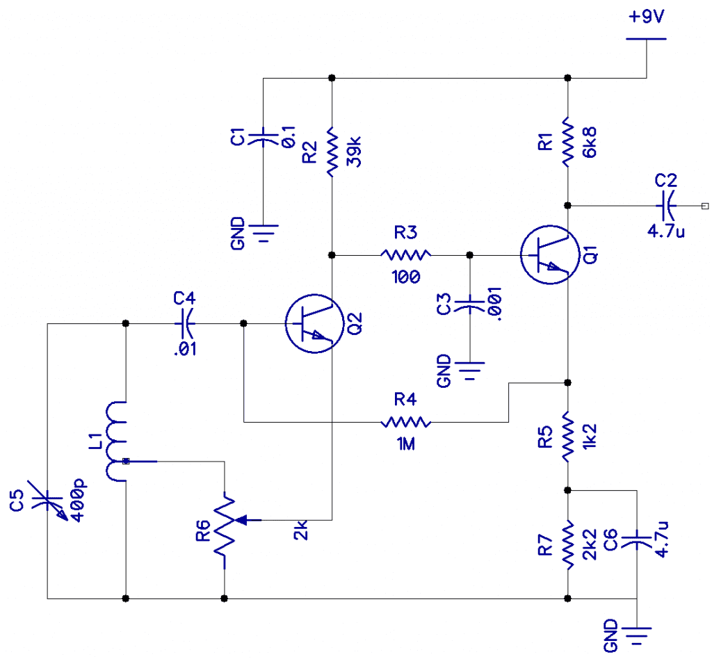
Rectification of the AM signal takes place inside Q2, and R3. Transistors Q1 and Q2 can be any NPN transistor. Capacitor C3 removes any remaining RF components. Some of the demodulated signals are fed back as positive feedback through R4 into the tap of L1 via the regeneration control R6. This will have the effect of starting to oscillate. The idea is to adjust potentiometer R6 to a point where oscillation is about to start and back off a bit. This has the effect of greatly increasing the sensitivity and selectivity of the receiver. R5 generates some negative feedback, which improves the audio quality.
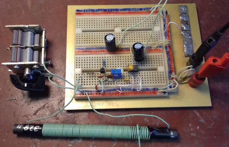
Variable capacitor C5 and coil L1 are the tuned circuit. Coil L1 is 60 turns on a 1 cm diameter ferrite rod (about 300uH) with 5 turns added for the tap. In the prototype board below, I am only using one half of the variable capacitor.
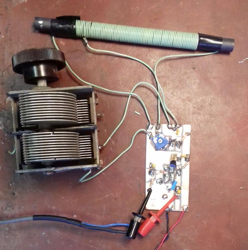 | 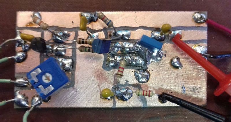 |
| Regenerative radio breadboard | Close up of the PCB |
LM386 Amplified AM Radio
The circuit below is basically the same crystal radio circuit as above, but the speaker has been replaced with an LM386 audio amplifier. This will allow the radio to work without an antenna or a good earth connection. Also, the LM386 provides enough amplification power to drive a small speaker.
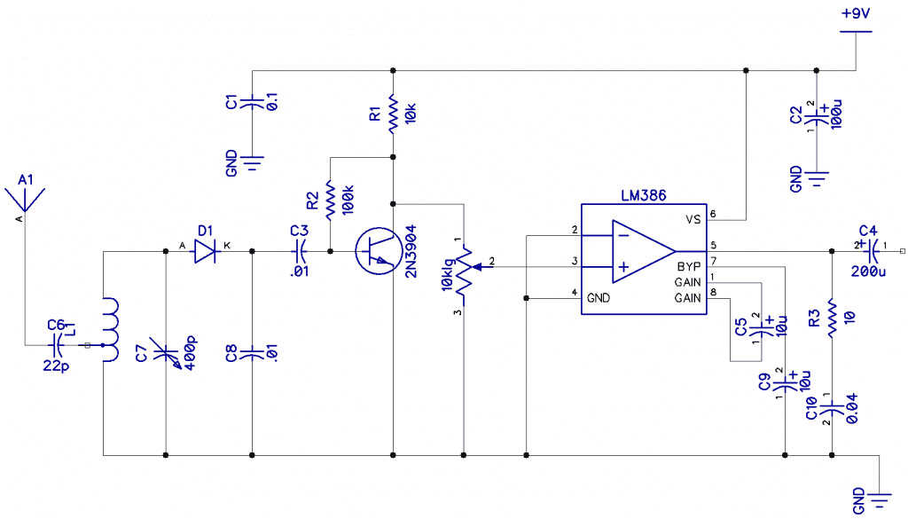
Capacitors C5 and C9 set the overall gain of the LM386. If you find the gain too high, you can adjust it following the instructions in our article on how to Build a Great Sounding Audio Amplifier (with Bass Boost). The article also discusses how to tweak an LM386 amplifier circuit to get better sound.
Resistor R3 and capacitor C10 prevent unwanted instability of the LM386’s output by providing a known load at frequencies above audio.
The 2N3904 transistor provides a moderately high impedance to the tuned circuit giving good selectivity.
 | 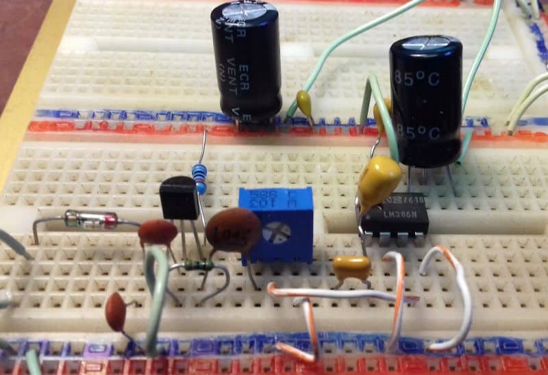 |
| Breadboard of the LM386 radio | Detail of the breadboard |
In conclusion, making your own AM receiver can be easy and gives a lot of rewarding listening pleasure. All of the above circuits were built and tested and worked pretty well.
And here’s a small tip, if you are unable to source a variable capacitor, you can make one by gluing aluminum foil to two sheets of A4 paper and connect them with crocodile clips. Sliding one sheet over the other makes a variable cap provided they don’t make electrical contact.
If you don’t want to go through the process of sourcing all of the parts for building these AM radios, there are some really cool DIY radio kits on Amazon.
Thanks for reading and be sure to leave a comment below if you have questions about anything!


For those running their own numbers for the frequency calculation on this page and getting the wrong value, the example:
F = 1/2π√((0.0003 H)*(0.000000000001 F)) = 919kHz
is wrong in that there’s too many zeros. 100pF is 0.000,000,000,1 (not 0.000,000,000,001).
I built the AM radio with LM386 amplifier twice. Absolutely did not work the first time. Took it all apart and started over thinking i made a mistake. Built it a second time and it still does not work.
Has anyone actually got this schematic to work?
[replying to Walt]
The circuit is a bit ambiguous.
Why is there a tap on the coil? Why is there an capacitor on the antenna? is it DC biased? What type of diode is used? The schematic shows all electrolytic caps but the pictures don’t. Why does the rectification happen before the base of the transistor?
Not sure I trust this circuit.
Hi A.W.,
I actually built this circuit recently and can confirm that it does work. However, I am going to update the article soon to include more information on how it works and the purpose of each component. The diode is germanium 1N34A. The 22 pF capacitor attached to the antenna is not necessary and the radio works better without it. The coil can be made by wrapping 98 turns of 26 ga magnet wire around a toilet paper roll (1.58″ diameter). The tap for the antenna should be at about 30 turns. It needs a long antenna too.
I have built this AM radio and it does work. Are you getting any static sounds? I had to use a 15 ft long wire antenna placed outside to pick up any radio stations. Also, having a good connection to ground is extremely important.