An audio mixer is a circuit for combining two or more analog signals so that they do not interfere with each other or cause loading on the source signals. They are mostly used to mix sound tracks from individual instruments like a microphone, guitar, and drums to create a master song track.

A professional-level mixer may have dozens of channels and settings for each channel, including presets, built-in effects, graphic equalizers, monitor controls, and output amplifiers to name a few.
But for this article, we are going to build a more simple, but still effective three channel stereo audio mixer.
Mixer Designs
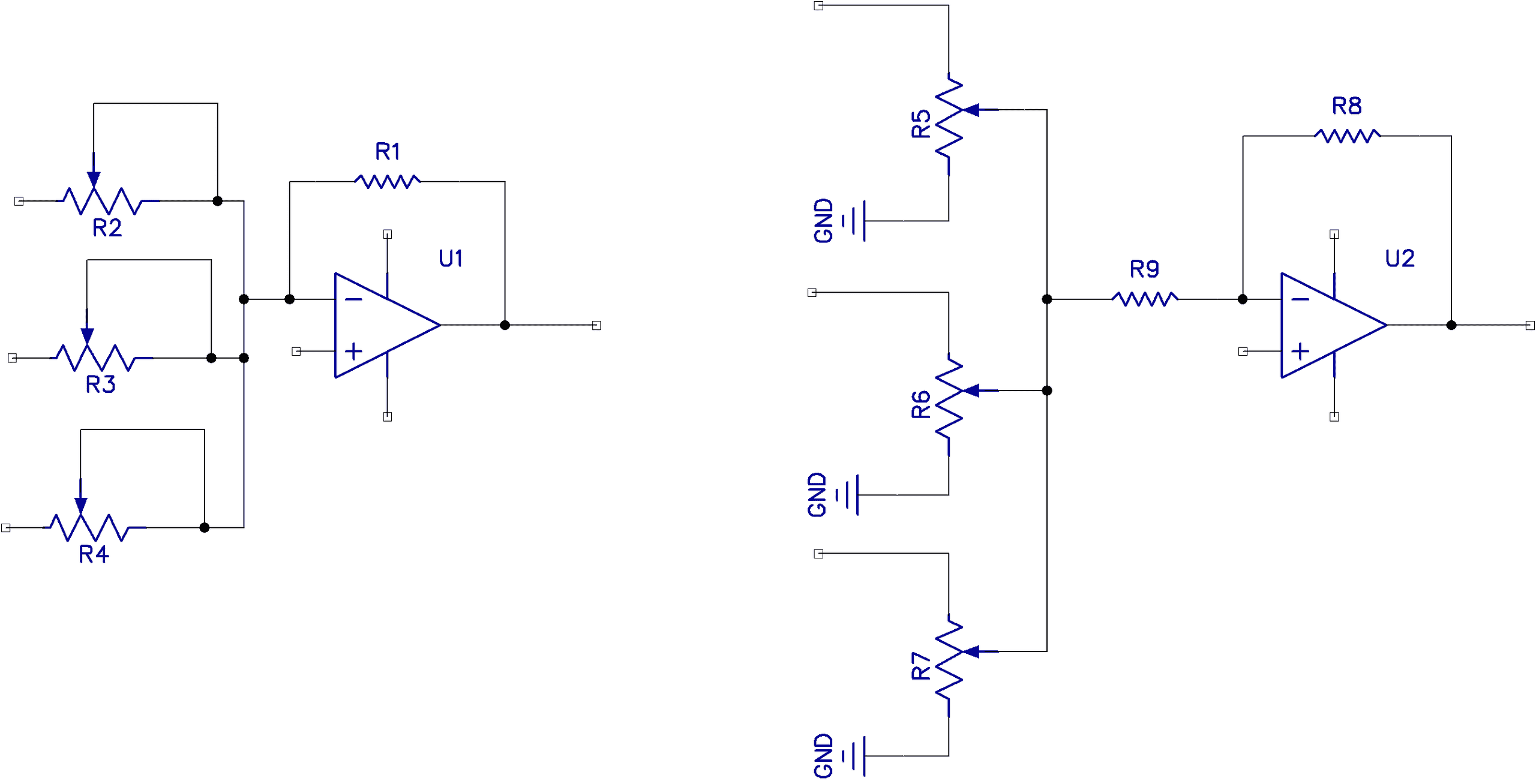
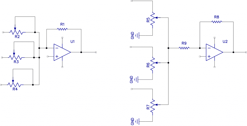
The basic idea behind a mixer is this: different inputs are fed into a common summing point, and these are added and then multiplied by the gain of the summing amplifier. Shown below are some input scenarios you may see on the internet. But I have avoided them for a couple of reasons.
The circuit on the left will have a varying input impedance depending on the slider setting, and the circuit on the right will cause a change in level on the adjacent channels when the slider is right down low. The circuit on the right does have the advantage of dealing with extreme input levels.
Our Design
For this tutorial, we will build a mixer of our own design. Our mixer will have two stages: one input pre-amplifier per channel and an output summing amplifier. The schematic below is for a mono three-channel mixer with a master volume. To make this a stereo mixer, simply duplicate the circuit for the other channel. They can share the same power supply.
Here is the schematic:
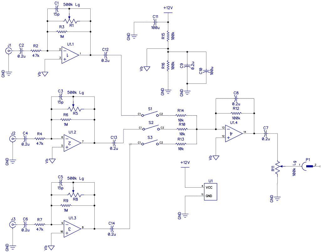
We want the input impedance presented to each input to be constant and not a function of the gain setting. So here, the input impedance will be 47k to match most audio sources and dynamic microphones. There will be three mono channels. The mixer will run on a single supply from a 12V power supply (this imposes a severe constraint on the range of signal headroom).
I used a common LM324 quad op-amp (not the best for low noise and some low noise quad op-amps might be quieter, but I had some lying around). The LM324 is designed for single-supply operation and has four separate op-amps. All four op-amps used in the circuit above are from a single LM324 chip.
1M Ohm resistors R3, R6, and R9 are in parallel with the input potentiometers. The purpose of this is to keep a constant DC bias on the op-amp and prevent slider noise.
Capacitors C1, C3, and C5 tailor the upper-frequency response to 20kHz, while the input capacitors C2, C4, and C6 tailor the lower frequency response to 20Hz.
Switches S1, S2, and S3 turn the channels off.
Resistors R15 and R16 divide the supply rail in half and provide a 6V bias voltage for all the non-inverting inputs. R11 is the main volume control. Note that all potentiometers should be the logarithmic type (audio taper).
How it works
LM324 op-amps U1.1, U1.2, and U1.3 are the input pre-amplifiers. Their function is to provide a suitable input impedance to the microphones and this is set to 47k by resistors R2, R4, and R7.
Potentiometer R1 sets the gain of the input amplifier. This potentiometer sets the actual level of each input as it will be presented to the summing amplifier. Resistor R3 is only there to prevent scratchy noise as the potentiometer is adjusted.
Capacitor C1 provides a high-frequency roll-off filter to keep out radio frequency interference and inaudible signal oscillations.
After the pre-amplification step, switches S1, S2, and S3 will allow us to mute any channel.
Resistors R14, R10, and R13 are the actual mixer part. The input to U1.4 is a virtual earth, which causes the virtual voltage at this point to be the sum of all three inputs. This is amplified 10 times by U1.4 because the gain of the op-amp is defined by the ratio of R12 to any one of the input resistors. Potentiometer R11 sets the final output level before it is sent to the output jack.
The gain of the summing amplifier is expressed as A = R12/R14 or 10X and the output of the combined inputs is Vout = -(A*V1+A*V2+ A*V3).
This can be simplified into -A(V1+V2+v3), thus called a summing amplifier.
Note that there is a minus sign there as the op-amp is working in its inverting mode.
Hope you build this three channel stereo audio mixer! Let us know in the comments below how it works for you!


The corner frequency of the summation amp in the proposed circuit seems much too low. The 0.2uF capacitor in parallel with the 100k feedback resistor is going to create a low-pass filter that will attenuate most audio frequencies.
I agree, the fc(LP) would be 16.93 Hz. The fc(LP) should never be lower than the fc(HP) – The HP would be 20k Hz which would be correct if it were the LP (and the Pot was set to 500K). I think your resistor and cap values are backwards. Switch C1 and R1 with C2 and R2. On top of that, the location of the pot should actually be before the HP cap and resistor. If you want a band pass filter, then the cap and the resistors should be permanent (no Pot) – unless you want to adjust the band pass, in that case, you are making a preamp.
Remember fc(LP) = 1/(2pi C1 * R1) – at least in your schematic – and it is where the frequency begins to drop off (the negative slop)
fc(HP = 1/(2pi C2 *R2) and it is where the slope is positive, and noise begins to be audible.
S1, S2, S3 should be after 10K resistors and should be two ways one side connected to the ground to mute, another to the summing opamp
Maybe the input signals’ ground should be Vb and not GND?
The input is referenced to the PS rail to give it more headroom, using Vb may introduce some clipping in some instances, although that might be ideal if you want some distortion type sound effects , which is what i’m currently looking into. Cheers.