A resistor is a passive two-terminal electrical component that limits the current flowing in electrical or electronic circuits. Its property to resist the flow of current is called resistance, expressed in ohm (Ω), named after German physicist Georg Simon Ohm.

Resistors are available in different sizes. Its size is directly proportional to its power rating. The power rating is the maximum amount of power that a resistor can dissipate without being damaged by excessive heat build-up. The larger the surface area covered by a resistor, the more power it can dissipate.
Types of Resistors
There are actually two types of resistors: fixed and variable.
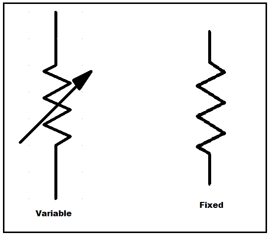
Fixed resistors are designed to set the right conditions in a circuit. Their values should never be changed to adjust the circuit since those were determined during the design phase. It can have a carbon composition or chip-and-wire wound type. It can also be made with a mixture of finely ground carbon or be very small in size and for high power rating.
Variable resistors have fixed resistor elements plus a slider. The slider taps onto the main resistor element so there will be three connections; two are connected to the third element and one to the slider. Examples of this are potentiometers, rheostats, trimmers, and so on.
How do resistors work?
Wiring a resistor in a circuit will reduce the current by a precise amount. If you look at resistors from the outside, they most likely look the same. However, if you break it open, you’ll see an insulating ceramic rod running through the middle with copper wire wrapped around the outside. Resistance depends on those copper turns. The thinner the copper, the higher the resistance since it’s harder for the electrons to pass through it. As we’ve found out, it’s easier for the electrons to flow in some conductor materials than insulators.
George Ohm studied the relationship between resistance and the size of the material that was used to make the resistor. He proved that the resistance (R) of a material increases as its length increases. This means that the longer and thinner wires offer more resistance. On the other hand, resistance decreases as the thickness of wires increases. Having said that, Georg Ohm came up with an equation that explains this relationship:
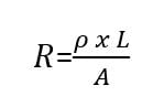
Note: Conductors have much lower resistivity than insulators. At room temperature, aluminum comes in at about 2.8 x 10⁻⁸ -Ωm, while copper is significantly lower at 1.7 x 10⁻⁸ Ω-m. Silicon has a resistivity of about 1000 Ωm and glass measures about 1012 Ω-m. Resistivity varies for different materials.
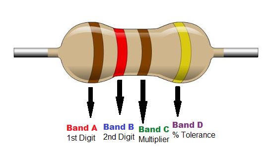
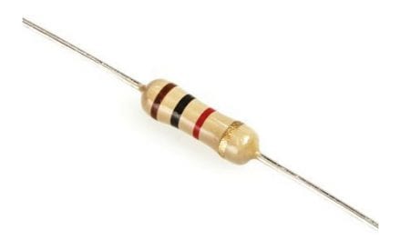
Resistor Color Coding
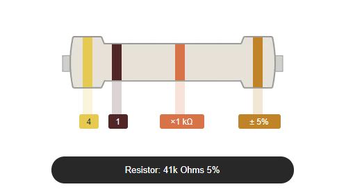
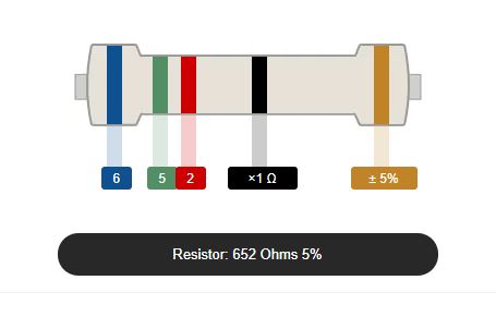
For a four-band color coded resistor, the 1st and 2nd band represent the 1st and 2nd significant digit while the 3rd band represents the multiplier, and the 4th band represents the tolerance.
For a five-band color coded resistor (high precision resistor), the 1st, 2nd and 3rd band represent the 1st, 2nd and 3rd significant digit while the 4th band is the multiplier and the 5th band is the tolerance.
For some four-band color coded resistor, another extra band (5th band) indicates the reliability in percent of failures per 1000 hours (1000h) of use.

SMD Resistors
SMD means Surface Mounted Device. It is used to create Surface Mount Technology. SMDs have small leads or pins that are soldered to pads on the surface of the board, instead of wire leads that go through the PCB. This eliminates the need for holes in the board and lets both sides of the board be more fully used. Since SMDs are too small, there is no room for traditional color band code to be printed on them. For this reason, new SMD codes were developed.
EIA-96 System
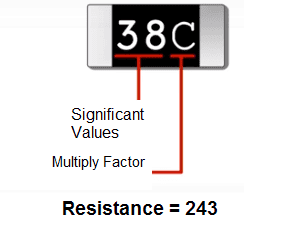
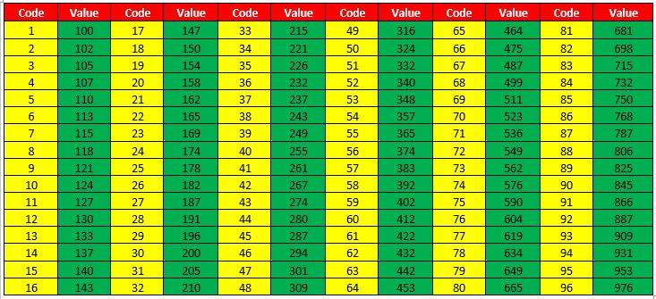
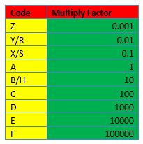
This system is based on the E96-series, thus aimed at resistors with 1% tolerance. Values are denoted by two (2) numbers, to indicate the resistor value and one (1) letter for the multiplier. The two numbers represent a code that indicates a resistance value with three significant digits. The tables below shows the value of each code. For example, 38C = 24300 Ω ±1%.
Three- and Four-Digit System
In this system, the first two or three digits indicate the numerical resistance value of the resistor, and the last digit gives a multiplier– the power of ten by which to multiply the given resistor value. For example:
- 273 = 27 Ω x 103 or 27,000 Ω (27 kΩ)
- 7992 = 799 Ω x 102 or 79,900 Ω (79.9 kΩ)
Note: The letter “R” is used to indicate the position of a decimal point for resistance values lower than 10 ohms. For example, 0R5 would be 0.5Ω, and 0R01 would be 0.01Ω.
Resistor Power Rating
Everytime a current passes through a resistor due to the presence of a voltage across, electrical energy is lost in the form of heat. The greater the current flow, the hotter the resistor will be. A resistor can be functional at any combination of voltage and current as long as it does not exceed the power rating that a resistor can convert into heat or absorb without any damage.
Resistor Power Rating is defined as the amount of heat a resistor can handle without sacrificing its performance in no definite time. In Ohm’s law, when a current flows through a resistance, a voltage is dropped across it producing a product that relates to power. In other words, if resistance is subjected to a voltage, or if it conducts a current, then it will always consume electrical power. Given this, we can say that these three quantities– power, voltage and current, are in a power triangle.
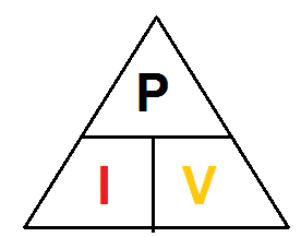
Using the Resistor Power Triangle is the best way to calculate the power dissipated in a resistor if we know the values of the voltage and current across it. Additionally, Ohms law allows us to calculate the power dissipation given the resistance value of the resistor. We can obtain two alternative variations of the above expression for the resistor power if we know the values of at least two among the three– voltage, current, and resistance.
Based on the power triangle, the electrical power dissipation of any resistor in a DC circuit can be calculated using one of the following three standard formulas:
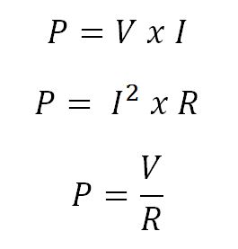
where V is the voltage across the resistor in Volts, I is current flowing through the resistor in Amperes, and R is the resistance of the resistor in Ohmss (Ω).
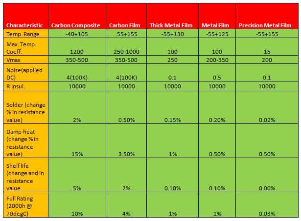
Types of Resistor Materials
Below are different types of resistor materials, their pros and cons, and their uses:
- Carbon film resistors are made up of a pure carbon film enclosed in an insulating cylindrical core, cut in a spiral to increase the resistive path. It is more accurate than carbon composite. However, in applications that require high pulse stability, special carbon film resistors are used.
- Metal film resistors are produced with tantalum nitride but more often, they are made using Nichrome. A combination of ceramic and metal is used as the resistive material. It has better stability, temperature coefficient, and tolerance than carbon films. Typical tolerances are between 0.5% and 2% with a temperature coefficient between 50 and 100 ppm/K. Stability is lower than wire-wound, but its high-frequency properties are better.
- Wire wound resistors are created using a winding resistance wire that has a spiral non-conductive core. The resistance wire is made up of nickel-chromium and the core is ceramic or fiberglass which has a coating protected with vitreous enamel. It is not suitable for applications higher than 50kHz since the spiral winding has capacitive and inductive effects. It is best used for high precision or for high power applications.
- Precision resistors have a thin bulk metal foil that is cemented on a ceramic substrate. It is the most accurate and stable type and it features a very low-temperature coefficient of resistance that is used for applications with high precision requirements.
- Metal oxide film resistors. The resistive material is usually a metal oxide such as tin oxide. It is useful in applications requiring higher endurance because it has a higher operating temperature that makes it more reliable and stable.
- Carbon composite resistors are made up of a mixture of fine carbon particles and a non-conductive ceramic material pressed in a cylindrical shape and baked. The resistance value depends on the dimensions of the body and the ratio between carbon and ceramic material. The more carbon you add, the lower the resistance. Carbon composition resistors are remarkably reliable but have poor accuracy with a maximum tolerance of around 5%.
Hope this has been useful! Leave a comment below if you have any questions…


Thanks
Thanks for giving a rundown on how resistors work! This is really helpful for those who are just getting started in electronics. Just curious. Which do you think is the best resistor material?
Hello Jenn, this was a great updater for me. I learned about electricity in High School back in 1965 so it has been a while.
I wonder if you could either answer my question or point me further. I have built a Hydrogen generator that is powered by a 12V, 30A automotive-type battery. I am not sure of the amperage I am pulling, from it but burns the lead wires. I realize I am essentially creating a short-circuit with the electrolyte, so I need to cut that current back somehow. I want to figure out the resistors I would need for that, but I don’t have quite enough knowledge to proceed. Can you help me?