In this tutorial, we will take a look at charging circuits for sealed lead acid (SLA), Nickel Cadmium (NiCd), Nickel Metal Hydride (NiMH), and Lithium Polymer (LiPo) batteries. We will provide schematics and instructions on how to build them.

But before we begin, please know that it’s important to charge batteries correctly. Using the wrong voltage or current, or the wrong type of battery charging circuit can make the battery catch fire or even explode. Exercise caution when using DIY battery charging circuits, and do not leave charging batteries unattended.
Sealed Lead Acid
Sealed lead acid (SLA) batteries are great if you have the space. Their large size allows them to maintain a charge on the shelf for a long time. SLA batteries are generally charged from a constant voltage source. The charger is set at a specific voltage that remains unchanged throughout the charging cycle. This allows the battery to initially demand a high current which then tapers off as it charges. The initial current has to be limited to prevent damage and overheating.
The side of an SLA battery usually has a label with a list of voltages to use for charging:
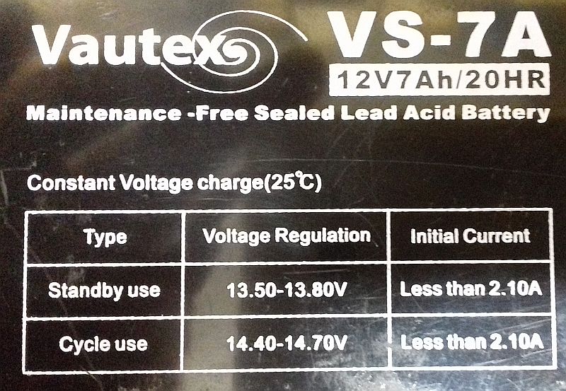
In the image above, there are voltage and current specifications for charging the battery in “standby use” or “cycle use”. Standby use refers to batteries that spend most of the time on a charger in a maintenance charge mode. Cycle use refers to batteries that are used frequently and charged often.
The initial charging current is shown for standby use and cycle use. The charge current should not exceed the value shown (2.1 A in this case). The charging voltage is different for standby use and cycle use modes.
In an SLA battery charger, the cyclic rate has to be monitored as at this rate; the battery will overcharge once it has reached capacity. Charging can be done with a current limiting benchtop power supply. Just set the voltage to the value you will use and set the current limit to the value specified on the battery.
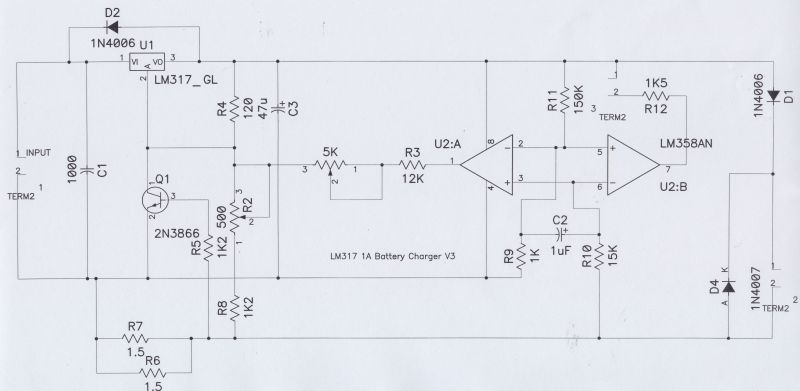
Shown below is a schematic for an SLA battery charger that automatically switches rate when the battery is fully charged:
Nickel Cadmium and Nickel Metal Hydride
Nickel Cadmium (NiCd) batteries have been popular over the last few decades, but they are gradually being replaced with Nickel Metal Hydride (NiMH) batteries. The reason is because NiMH batteries have less charge memory compared to NiCd batteries.
NiCd and NiMH batteries have similar charging requirements. Both types offer the ability to charge as many as you like in series. Both can be charged with a constant current.
This is a schematic for building a discrete transistor charger, which can be used to charge NiCd and NiMH batteries:
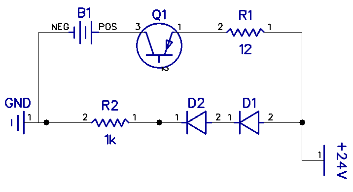
This circuit is designed to charge a 12V battery at 50mA, but it can be easily scaled up to higher voltages and currents with suitable components.
Diodes D1 and D2, and resistor R2 provide a constant voltage of 1.2V at the base of Q1, as the base-emitter voltage will always force 0.6V. By choosing R1 correctly, we have a programmable constant current source. To calculate the value of R1 that will provide a particular current, use this formula:
R = V / I
In this case, V is 0.6 volts and the charge current will be 50 mA, so:
R = 0.6V / 50mA
R1 = 12Ω
The schematic below is for an LM317 adjustable voltage regulator configured as a constant current source. This charger can charge both NiCd and NiMH batteries:
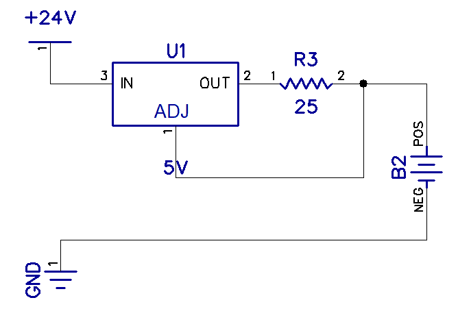
The circuit is designed to charge a 12V battery at 50mA.
The LM317 forces a 1.25V reference voltage between Vadj and Vout. To calculate the value of R3 to give a particular charging current, use this formula:
R = V / I
So with V at 1.25 volts and I at 50mA,
R = 1.25V / 50mA
R3 = 25Ω
Lithium Polymer
Lithium Polymer (LiPo) batteries are popular in RC models, laptops, and power banks because they can have high voltages and a large capacity for their size.
LiPo batteries require careful and controlled charging. LiPo batteries should not be charged in series. A proper LiPo charging cycle consists of four sequential charging stages:
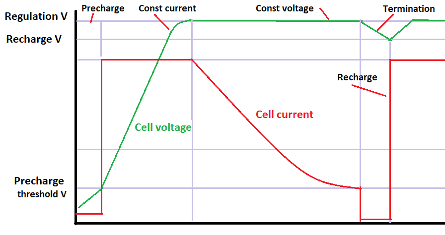
After a fully discharged LiPo battery is connected to the charger, the first stage is a pre-charge stage. During this stage, the charge current is set to 10% of the maximum charging current. In the next stage, a constant current is applied to the battery while the voltage increases steeply. The voltage eventually levels off into the third stage, where a constant voltage is applied to the battery. In the final stage, the current starts to tail off. When the charge current becomes 10% of the maximum charging current, the charging is terminated:
LiPo batteries can be charged with a TP4056 lithium battery charging module. The module can be powered by the 5V provided by a micro USB cable, or via contacts on the PCB.
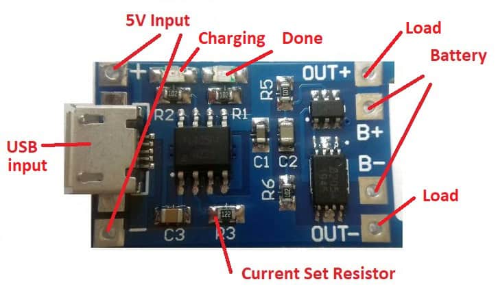
When the battery is fully charged, the green LED will light up. The battery is connected to the B+ and B- pins. There are also OUT pins, which can be used to incorporate the charger into another circuit. The module monitors and will prevent over-discharge as well.
Although making a charger is not too complicated, always remember use caution at all times. Batteries that are not charged correctly can catch fire or explode. That said, making the battery chargers above can be extremely useful in a wide variety of DIY electronics projects.
Thanks for reading and feel free to leave a comment below if you have questions about anything!

I was all excited thinking you were going to detail all the relevant charger circuits, so what happened to LifePo4 battery charging 3.2-volt output
Hi,
If a battery charger connected to the terminals of a battery (say an SLA battery) is turned off, will the battery eventually drain by being connected to the battery charger? i.e. is there a parasitic load/loss in the charger itself if not powered up? Is this a significant level of loss?
Thanks
Ben