If any of the projects you create are designed for portability or remote monitoring use, it usually requires the use of creative power sources. Solar power can often be a useful solution for powering such devices. In this tutorial, we will discuss how to select the proper solar panel based on your power requirements, particularly for projects using the Arduino. We will also touch on power management and charge controllers.

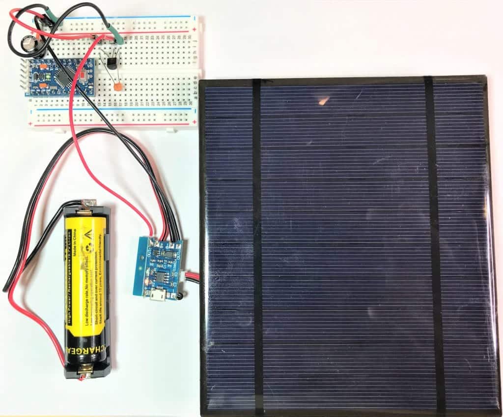
Components needed for this project:
- Arduino Pro-Mini, or Arduino Nano
- TP4056 battery charge controller
- 100 uF capacitor
- 100 nF capacitor
- MCP1700-3302E 3.3V voltage regulator
- 3.7V 18650 Lithium Ion battery (2000 mAH or more)*
- 6V DC, 500 mA solar panel*
- Breadboard
- Jumper wires
*Actual values will depend on your project’s power requirements.
Selecting the Right Arduino for Your Project
In this exercise, we will compare the three different Arduino boards to see which one best fits your needs. Listed here are the various attributes used to determine the best suited for our example.
The Arduino UNO will be our benchmark platform. Let’s start by listing the attributes and then compare the three boards.
Arduino UNO
- Microcontroller ATmega328P, 8-bit AVR family microcontroller
- Operating voltage: 5V DC
- Input voltage 7 – 12V DC
- Analog inputs: 6
- Digital I/O: 14, 6 PWM
- SRAM: 2KB
- EEPROM: 1KB
- Flash 32K
- Clock Speed: 16 Mhz
- USB connection
- Power (idle) 50 mA
- Size: 2.7″ X 2.1″
Arduino Nano
- Microcontroller ATmega328P, 8 bit AVR family microcontroller
- Operating voltage: 5V DC
- Input voltage 7-12V DC
- Analog inputs: 8
- Digital I/O: 22, 6 PWM
- SRAM: 2KB
- EEPROM: 1KB
- Flash 32K
- Clock Speed: 16 Mhz
- USB Connection
- Power (idle) 19 mA
- Size: 1.7″ X .73″
Arduino Pro-Mini 3.3 V
- Microcontroller ATmega328P, 8 bit AVR family microcontroller
- Operating voltage: 3.3V DC
- Input voltage 3.3-12V DC
- Analog inputs: 6
- Digital I/O: 14, 6 PWM
- SRAM: 2KB
- EEPROM: 1KB
- Flash 32K
- Clock speed: 8 Mhz
- Power (idle) 4.7 mA
- Size: 0.7″ X 1.3″
All three boards incorporate the same microcontroller. They have nearly the same number of analog ports, digital ports, PWM ports, and memory configuration. The most significant variation is in the clock speed, power requirements, and the physical size of the boards.
The primary objective in designing a device running in solar power would be to reduce power consumption. With that objective and the attributes given above, we now compare and choose between Arduino Uno, Nano, and Pro Mini.
An Arduino Uno draws approximately 50 mA over 2 1/2 times what a Nano requires at 19 mA. The Pro Mini with 4.7 mA brings 11 times less than an UNO. And comparing the three, Pro-Mini is considerably smaller and less expensive.
Clock Speed of the Pro-Mini
Apart from the power consumption, the big difference is the clock speed of the Pro-Mini. This slower clock speed accounts for the most significant decrease in power needed for the Pro-Mini. Depending on your application, this may or may not adversely affect the circuit.
Another difference is that the Pro-Mini does not incorporate a USB host controller. This omission requires you to use an FTDI controller to program the Pro-Mini, possibly adding some cost to your project. Eliminating the USB controller power consumption is lowered as well as overall price and size.
In your design, you can use Nano if you need the extra clock speed, or possibly need to attach 5-V peripherals. There is also a 5-volt Arduino Pro-Mini available that runs a 16 Mhz clock. If you decide to use a 5V Arduino, simply add a boost converter after the 3.3V supply (Amazon Model XL6009 DC to DC converter). But for this exercise, we will use the 3.3-V Pro-Mini.
Charge Reservoir (Battery Source)
Many rechargeable batteries are available to run the Pro-Mini. For this example, we will use a lithium-ion battery that provides a 3.7-V source from a single cell.
When deciding to use a lithium-ion battery, safety factors must be considered. Take note that lithium-ion batteries, if misused or mishandled, can catch fire or blow up. It is necessary to take extra precautions considering the battery has a high amount of energy and volatile chemical content.
To avoid these potential problems, lithium battery charge controllers have been designed to safely control the charging and discharging rates.
Battery Charge and Protection
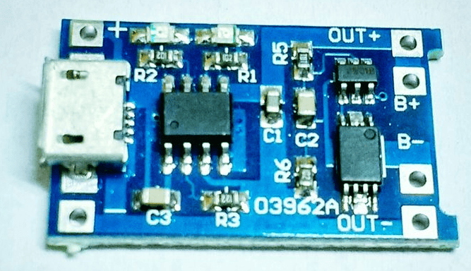
TP4056 Battery Charge and Protection module addresses the following concerns around charging and maintaining lithium-ion batteries:
- Manages constant current to constant voltage charging of a connected lithium battery
- Over-discharge protection – prevents the battery from discharging below 2.4V.
- Overcharge protection – safely charges the battery to 4.2V.
- Overcurrent and short-circuit protection – cut the output from the battery if the discharge rate exceeds 3A or in the event of a short-circuit.
- Trickle charge (battery reconditioning) – the voltage level of the connected battery is less than 2.9V. Also, the module will use a trickle charge current of 130mA until the battery voltage reaches 2.9V. At that point, the charge current will be linearly increased to the configured charge current.
- Soft-start protection – limits in rush current.
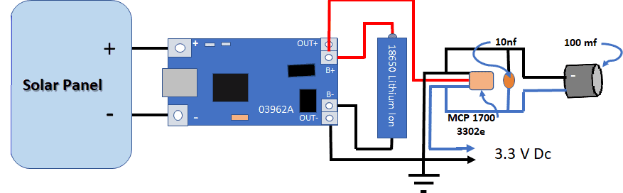
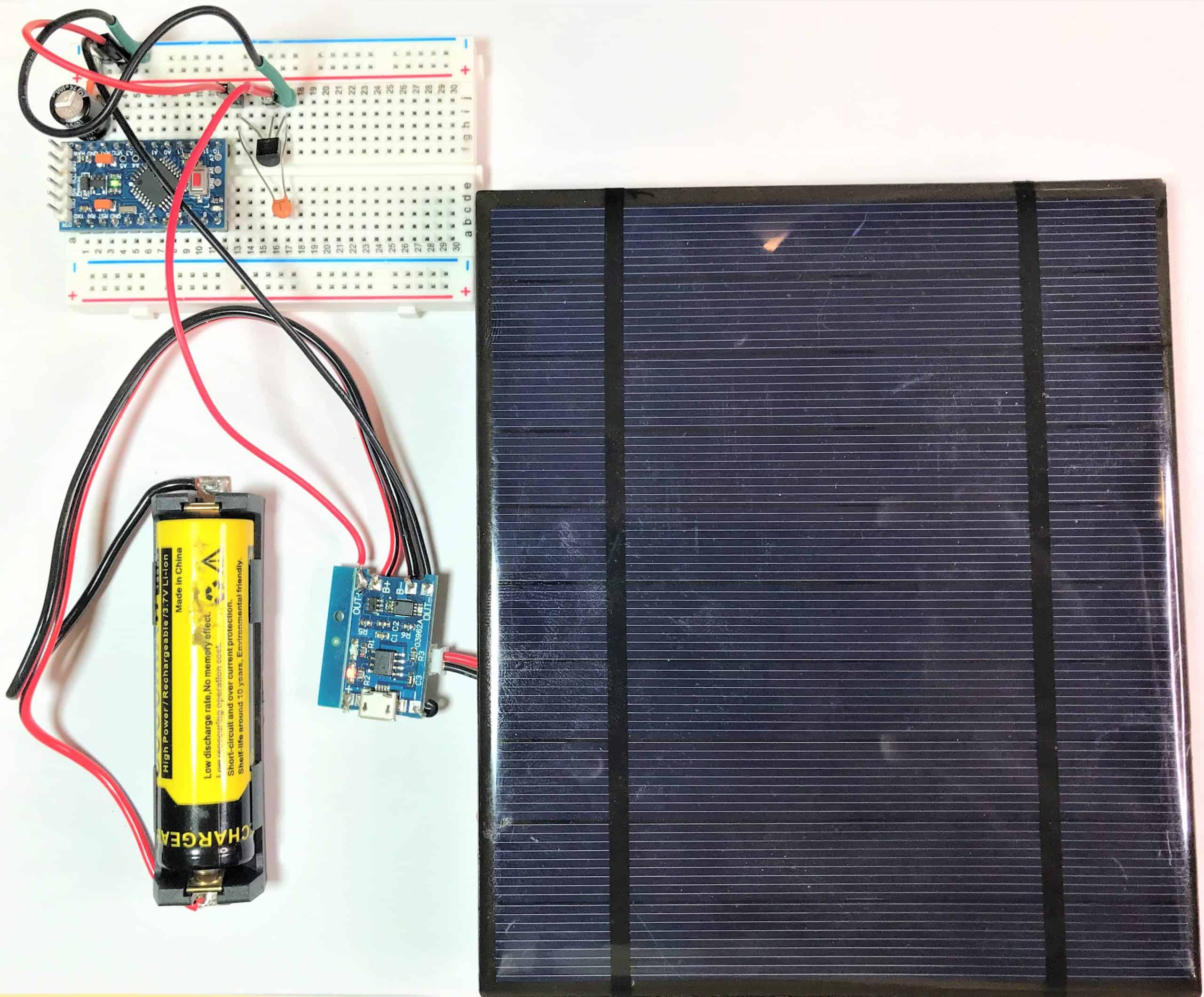
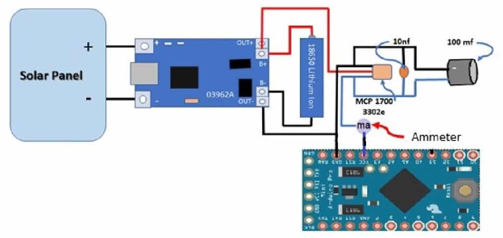
This configuration charges the battery as well as supply power to the circuit when the solar cell is producing energy. At night, the charge circuit disconnects, and the battery is used as the power source for the circuit.
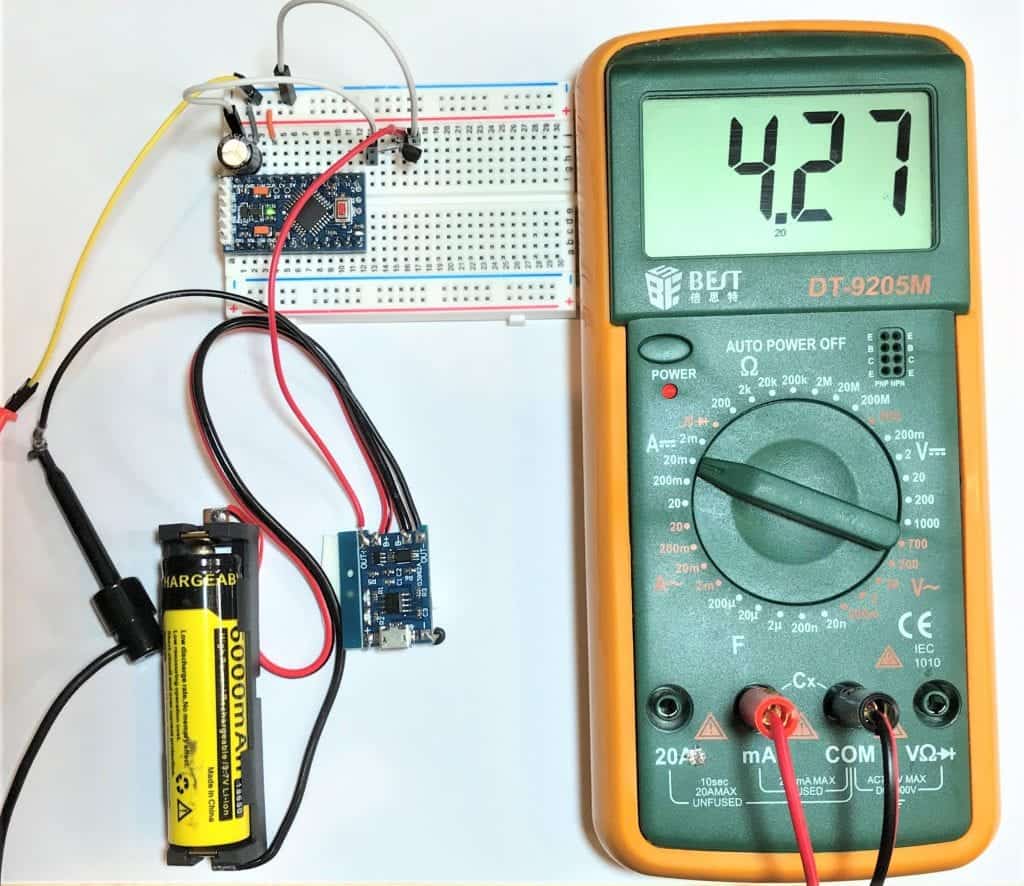
The 03962A charge controller also allows charging from a 5-V cell phone charger (USB mini cable). The MCP1700 effectively regulates the voltage to the required 3.3 V for the Pro-Mini. Two capacitors are used to eliminate noise and smooth out the output voltage. Notice that the 100 uF capacitor has a polarity.
Lithium-Ion Batteries can be connected in parallel if both batteries are identical. Its operating temperature is 10°C to 55°C while charging temperature is 5°C to 45°C.
If you want to learn more about the Arduino, check out our Ultimate Guide to the Arduino video course. You’ll learn basic to advanced Arduino programming and circuit building techniques that will prepare you to build any project.
Selecting the Solar Cell and Lithium battery
Taking into account the power requirements of your completed circuit, you can begin to design the power circuit.
We begin with the assumption that your device will be used remotely, running 24 hours a day, seven days a week. You should use the day with the least sunlight in 24 hours – December 21. And to help you determine the amount of sunshine in your area, you may refer to this website: http://latlong.net.
After calculating your latitude, you may refer here to see how many hours of daylight you can receive in December. In my case, the chart shows that during December solstice, the sun shines 10 hours a day in San Antonio.
The next calculation that you can check here determines the rate by which you can expect the sun will be shining, taking into account overcast days. For my location, I can expect 67% of the time on December 21, receiving 10 hours of sunlight.
Calculating Solar Panel and Battery Sizes
Now, we will calculate the size of the solar panel and battery to power my circuit that draws 23 mA. Using the percentages calculated above, this means I will have 6.7 hours of sunlight for charging time on the shortest day of the year (67% of 10 Hours = 6.7 hours).
Given the calculation above, my circuit will draw 522 mAH/day (23 mA x 24 Hours = 522 mAH/day). If we have 6.7 hours of sunlight, then the power supply must deliver 82 mAH (552 mAH / 6.7 Hours of daylight = 82 mAH). To be on the safe side and to account for two heavily overcast days, we should be double the rate (82 mAH X 2 = 164 mAH).
Given these, we must choose a solar panel capable of at least 5-7 V @ 164 mAH, and a Lithium battery rated at 1044 mAH. To be conservative, my solar panel is rated at 6 V @ 500 mAH; the lithium-ion battery is rated at 2000 mAH.
Let us know in the comments how you plan on using this solar powered Arduino! And feel free to leave a comment if you have questions about anything!

Hi there. I’m a bit confused by this. I have read on a couple of other websites that you can’t hookup a solar panel and battery with a load such as arduino this way as the TP4056 will continue to try and charge the battery due to the TP4506 not being able to detect when the CC has fallen below the C/10 threshold. That you need to disconnect the load from the battery prior to charging as shown here.
https://www.best-microcontroller-projects.com/tp4056.html
However I have also been researching and the method in the web page I have linked to apparently does not work well with Solar panels.
Hi,
Any response to Bob’s question above? I would like to try this project but wanted to first make sure that it’s safe to do.
Thanks
I have read these articles (suggesting that one shoujld not charge a battery while under load), but I’ve had nodes running more or less in this configuration for well over 12 months now (see http://digitalconcepts.net.au/pcbs/index.php?op=iot) and I haven’t noticed any problems. My nodes are sleeping most of the time, so maybe that is a consideration, but my batteries stay pretty much fully charged.
Thanks for sharing such informative article. We are solar consulting agency and this article increased our knowledge about where else we can use solar panels more
Ik heb hiervoor twee zonnepanelen van elk 3 watt in serie gezet, waardoor ik 6 watt verkrijg. Beide zijn van 6 volt. Maar als ik 1 paneel plaats meet ik 5 volt bij een bepaalde lichtintensiteit. Maar als ik beide in serie plaats, meet ik ook 5 volt bij eenzelfde lichtintensiteit. Ik heb nog nooit meer dan 5 volt gemeten. De uitgang van de panelen gaan naar een buck converter die de ingaande spanning omzet naar 5 volt. Weet iemand dit te verklaren en hoe ik aan meer dan 6 volt kan geraken?
i have tried many arduinos for solving the Problem to power with Solar Panel without the use of a batterie. the only one i have found was arduino yun mini. The device has well restart behaviour under unstable voltage conditions
Li-Ion batteries should not be recharged if the temperature is below 10°C. Do you have any recommendation on what kind of batteries and charging module use to power and recharge the Arduino from a solar panel in locations where is -20°C in winters?
Good evening,
I’m currently designing/working on a cubesat. I currently have a “Seeed Studio 0.5W Kit solar panel” solar panel, and “7.4V 2.25Ah Lithium Ion Battery Pack with JST Connector – 18650CA-2S-3J” battery.
I am having trouble finding a suitable battery charger and protection module. I was wondering if you have any recommendation or information on where I can look.
Thanks,
Jordan