The Arduino is an electronics prototyping platform that makes it easy to build fun and useful projects, learn about electronics, and quickly test new ideas. In this article we will take an in-depth look at each part of the Arduino Uno’s PCB to get a better understanding of how the Arduino works at the hardware level.

The ATMEGA328 Microcontroller
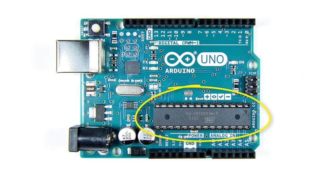
The heart of the Arduino is a microcontroller called the ATMEGA328. The ATMEGA328 was originally intended for industrial automation systems, and working with it directly requires advanced electrical engineering and programming skills. The Arduino was designed to make programming and connecting devices to the ATMEGA328 microcontroller much easier.
The ATMEGA328 microcontroller is attached to the PCB with a female pin socket so it can be removed from the PCB:
GPIO Pins
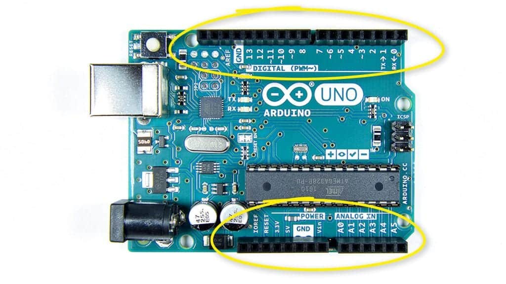
The pins on the top and bottom of the board are general purpose input and output (GPIO) pins. GPIO pins are used to connect external circuits, sensors, and other devices to the Arduino:
Digital Pins
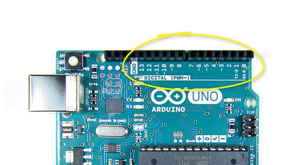
Digital pins can supply a high (5V) or low (0V) signal to external components and devices. Some of the digital pins have special functions that will be explained below. The digital pins are labelled 0 to 13:
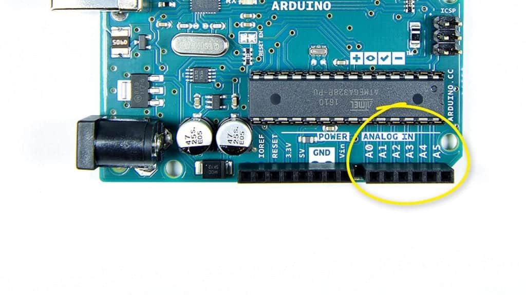
Analog Pins
The analog pins can generate or detect any voltage between 0V and 5V. They are labelled A0 to A5:
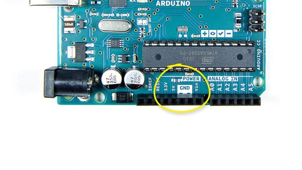
Power and Ground Pins
The power and ground pins can supply 5 volts or 3.3 volts to external devices and circuits:
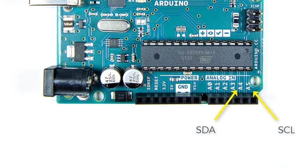
SDA and SCL Pins
The SDA and SCL pins are used for I2C communication:
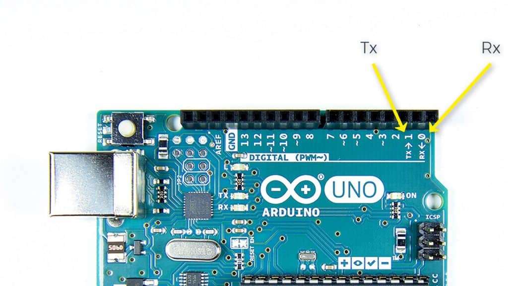
Tx and Rx Pins
The TX and RX pins are used for UART communication:
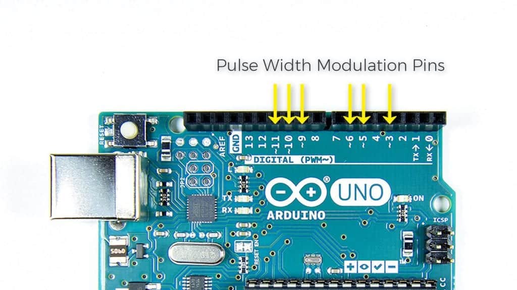
Pulse Width Modulation Pins
The pins labelled with squiggly lines are pulse width modulation pins:
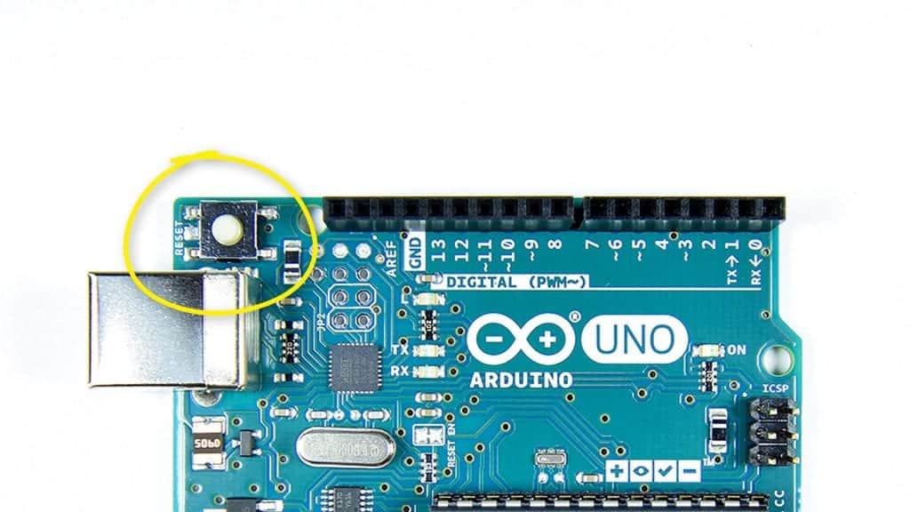
Reset Button
The reset button re-starts the Arduino and makes the sketch start over from the beginning:
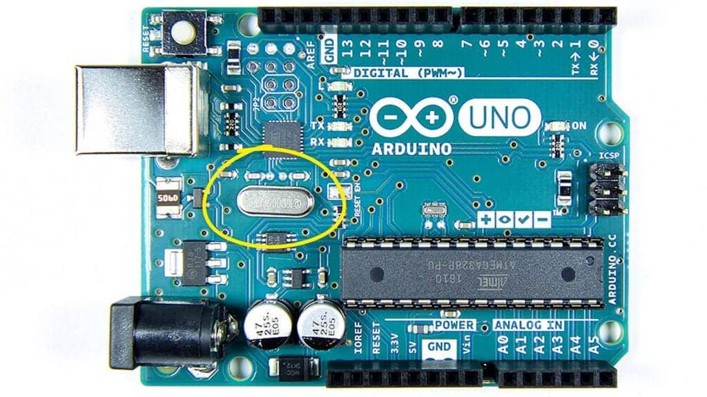
Crystal Oscillator
The crystal oscillator gives the Arduino the ability to keep track of time and generate pulse width modulation and serial communication signals. The crystal oscillator is 16 Mhz, which means the Arduino can execute binary instructions at 16 Mhz, or 16 million times per second:
Power Supply
The power supply is in the lower left side of the Arduino’s PCB:
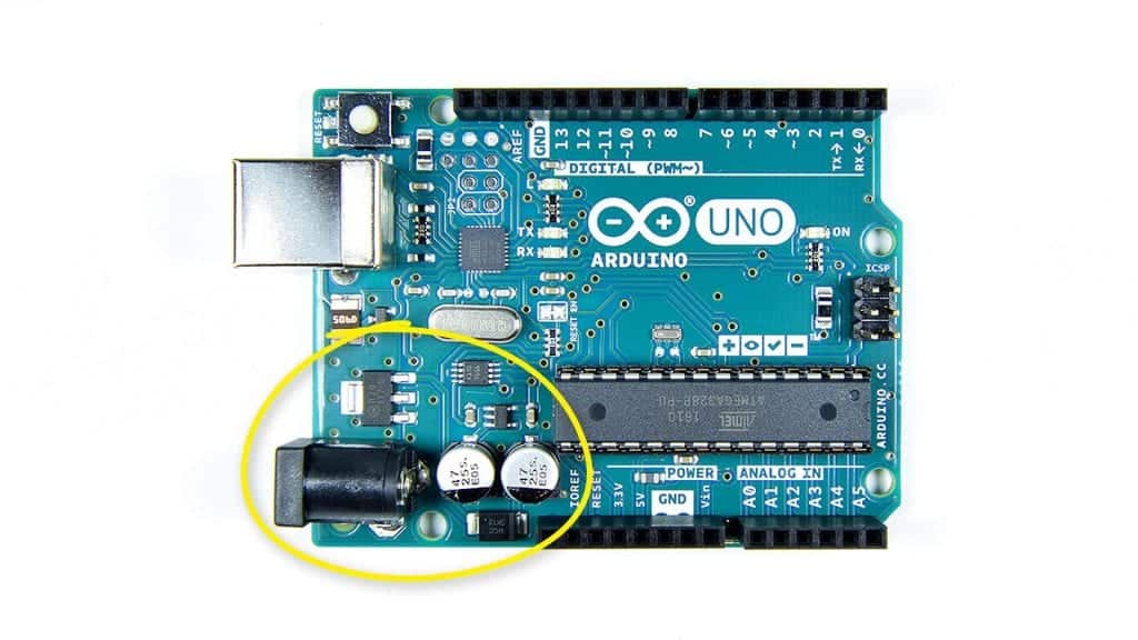
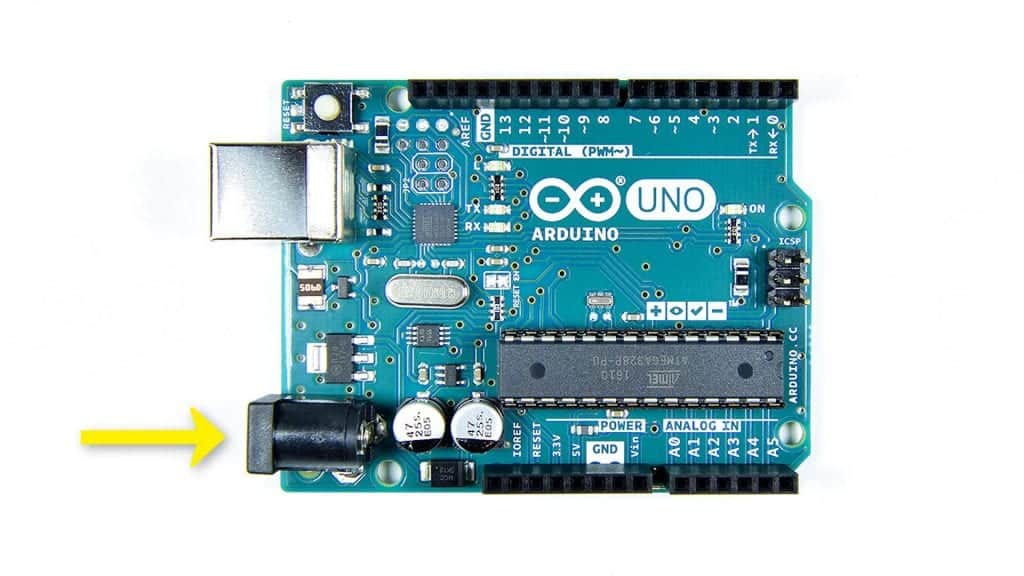
Power Input Jack
The Arduino can be powered from the 5V supplied by the USB cable. But for running the Arduino away from a computer, it can be powered by a 7 to 12V AC to DC power supply adapter. The power adapter connects to the Arduino through the power input jack:
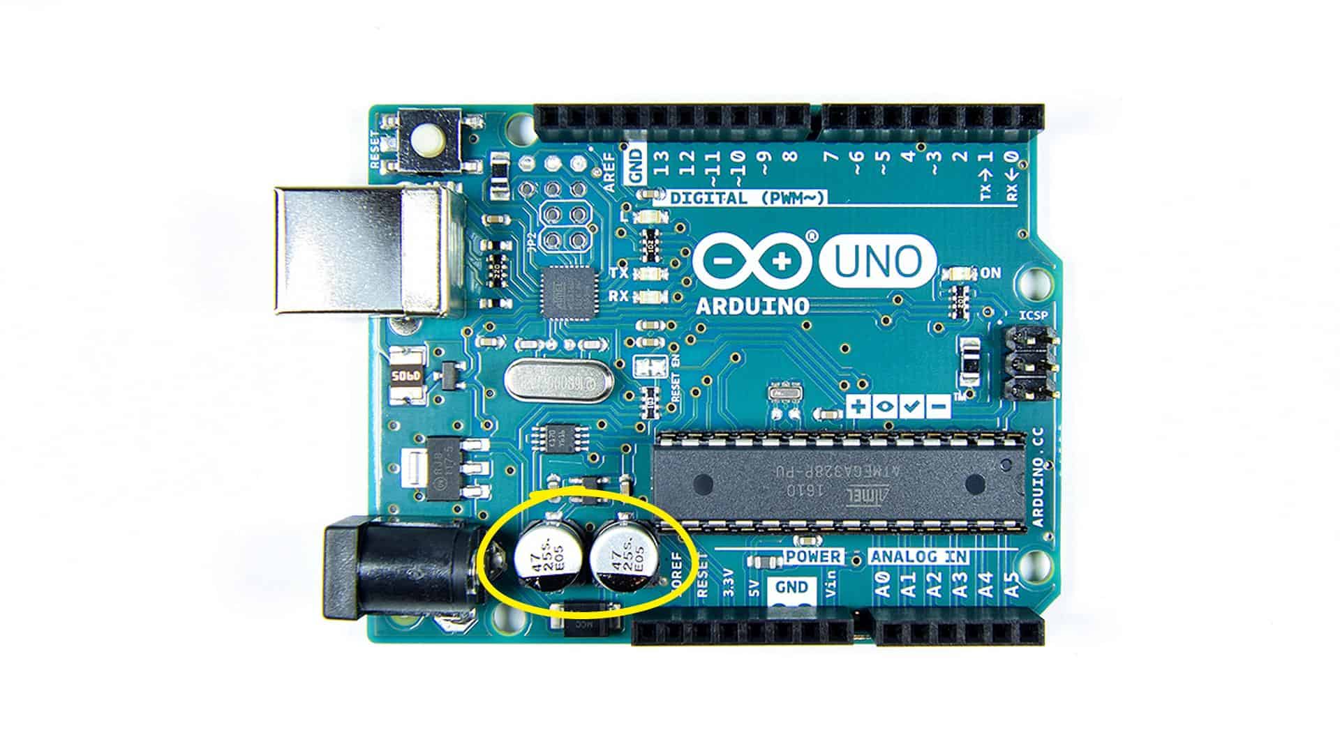
Power Supply Decoupling Capacitors
The power supply decoupling capacitors filter the incoming power supply to reduce voltage spikes that could damage the board:

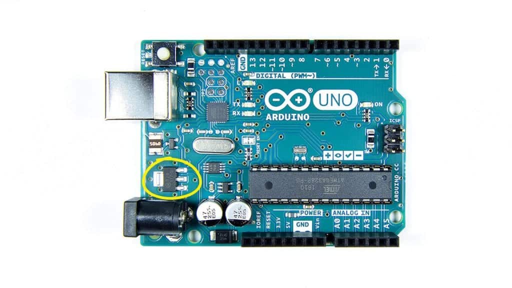
Voltage Regulator
The voltage regulator steps down the 7 to 12 volt input power to 5 volts, which is the operating voltage of the Arduino:
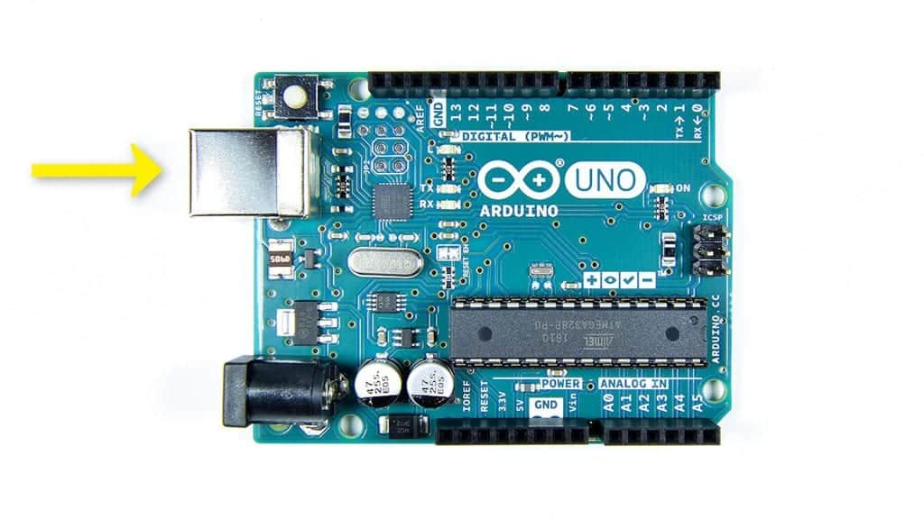
USB Connector
Programs are uploaded from your computer to the Arduino using USB communication. Serial data generated by the Arduino is also sent via USB to your computer when it is displayed on the serial monitor. The USB cable can also power the Arduino while it is connected to your computer. This is the connector for the USB cable:
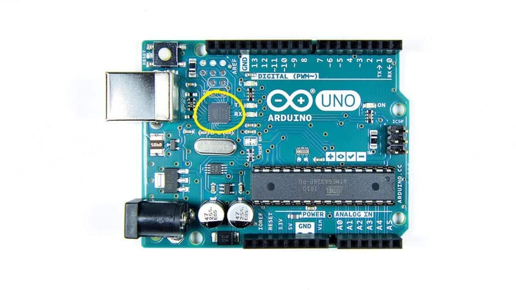
USB Control Chip
The USB control chip is an ATMEGA16U2 microcontroller. It controls all of the USB communications between the Arduino and your computer:
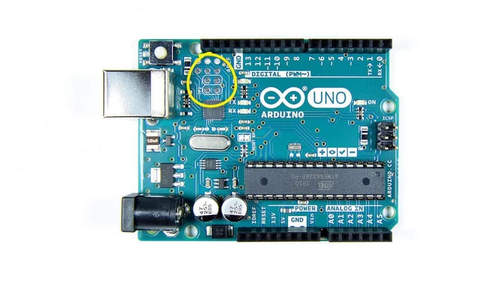
USB Control Chip Programming Pins
This group of pins is the in circuit serial programming header (ICSP header) for the USB controller. These pins are used for programming and re-flashing the firmware on the ATMEGA16U2:
ATMEGA328 Programming Pins
These pins are the ICSP pins for the ATMEGA328. They’re used for programming and re-flashing the firmware on the ATMEGA328:

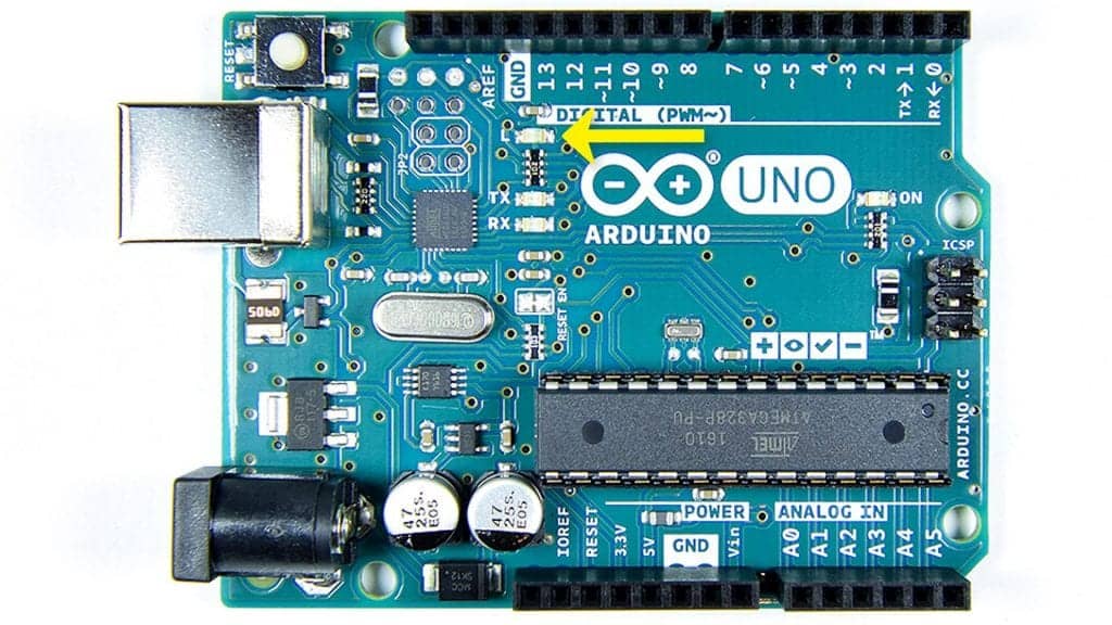
Pin 13 LED
This is a surface mounted LED which is connected to digital pin 13. Whenever pin 13 is in a high voltage state the LED will light up:
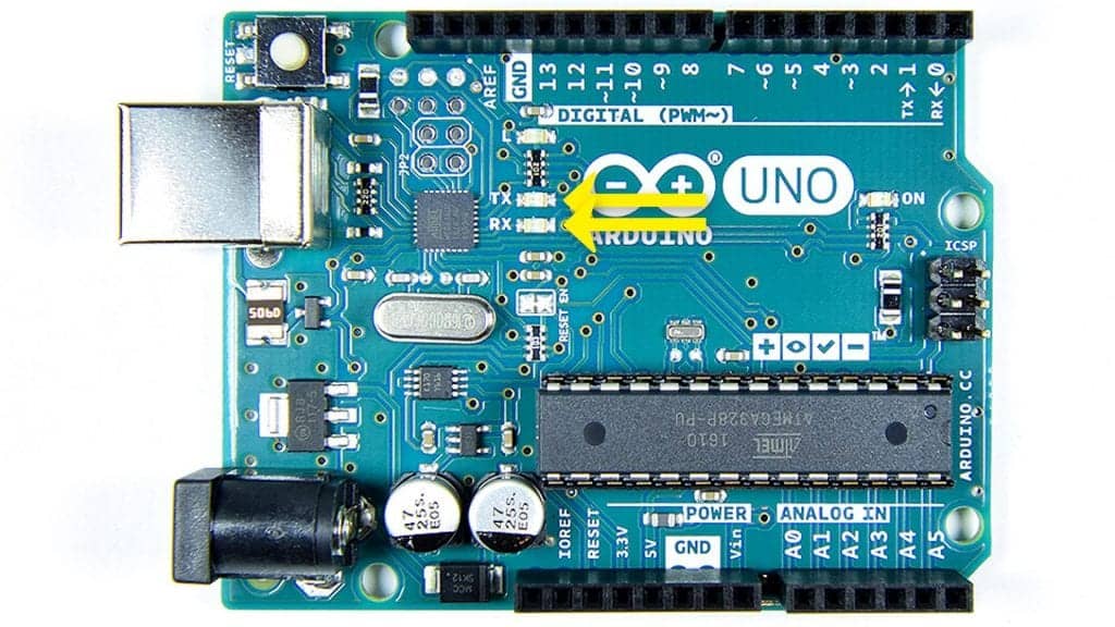
Tx and Rx LEDs
The TX and RX LEDs light up whenever data is transferred between the Arduino and your computer:
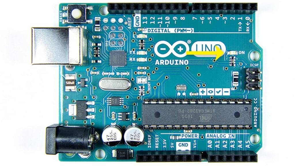
Power LED
The power LED turns on when the Arduino is powered up:

very clearly explained
You got me excited when I read “The analog pins can generate or detect any voltage between 0V and 5V.” Here I was thinking the ATMEGA328P actually included a D/A converter beyond the PWM stuff. I just went tearing through the data sheet thinking I’d missed it all these years. Alas, it was not to be. The analog pins can detect the voltages, but not generate them.
Good for me and give me a acknowledge about arduino uno microcontroller .