A transformer is an electrical device designed to transfer electrical energy from one circuit to another at the same frequency. It is also referred to as a static machine since it does not have any moving parts. It is used to control the voltage levels between circuits. It has three main parts which consist of two windings and a metallic core to which the windings are wound. These windings are in the form of coils made up of good current conductor materials. The windings in a transformer play a main role in the machine as these winding coils serve as inductors.

Anatomy of a Transformer
A transformer consists of the following parts:
- Primary coil
- Secondary coil
- Core
- Insulating materials
- Transformer oil
- Conservator
- Breather
- Tap changer
- Cooling tubes
- Buchholz Relay
- Explosion vent
How Transformers Work
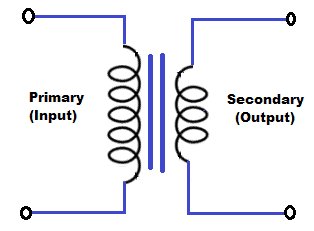
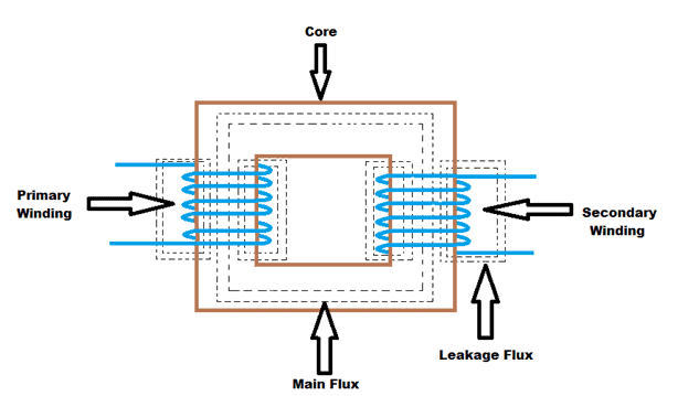
The primary coil, secondary coil, and the core are the main parts of a power transformer. These parts are very important for a transformer to function.
The primary coil is usually made up of copper for its high conductivity and ductility. The number of turns of the coil should be a multiple of the number of turns in the secondary coil. It is also responsible for producing magnetic flux. Magnetic flux is produced when the primary coil is connected to an electrical source. The copper conductor used in the primary coil should be thinner than that of the secondary coil so that the current in the secondary coil will be higher than that of the primary coil.
The secondary coil, which is also made up of copper, receives the magnetic flux produced by the primary coil. The flux passes through the core and links up to the secondary coil. The secondary coil delivers the energy to the load at changed voltage. The voltage will be induced in this coil so the winding should have a higher number of turns compared to that of the primary coil. The current coming from the primary coil will generate an alternating magnetic flux in the core to cause an electromagnetic connection between the primary and the secondary coils. The magnetic flux which passes through the two coils induces an electromotive force with a magnitude that is proportional to the number of turns of the coil.
Coil Wire Wraps and Output Voltage and Current
The amount of induced voltage caused by the induced current in the secondary coil depends on the number of coil wraps in the secondary coil. The relationship between the wire wraps and the voltage in each coil is given by the Transformer Equation:
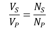
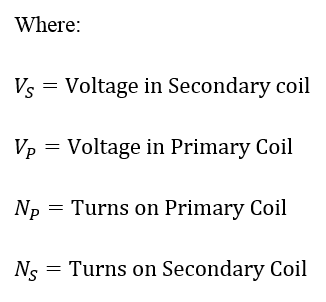
The transformer equation shows that the ratio of the input and output voltages of a transformer is equal to the ratio of the number of turns on the primary and secondary coils.
Calculating the Input and Output Voltage/Current as a Function of the Primary and Secondary Wire Wraps
The relationship of the input and output current and the coil wraps of the transformer is given by:
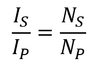
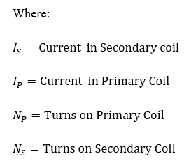
The given equation shows that the ratio of the input and output current of the transformer is equal to the ratio of the number of turns of the two coils.
Evaluating the two equations above, we can conclude that if the voltage increases, the current decreases. In the same way, if the voltage decreases, the current increases.
What is a VA rating?
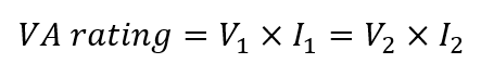
A VA rating or volt-ampere rating is commonly used to determine the amperage at a given voltage in a transformer. Volt-ampere is also used for the apparent power in an electrical circuit. This rating determines how much volt-amp a transformer is capable of delivering.
Determining the VA and Calculating the Max Current for Primary and Secondary Windings
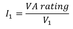
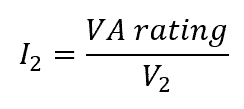
To calculate the primary and secondary winding current of a transformer with a given VA rating, we use the following:
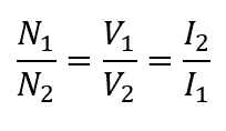
For the relationship of the number of turns, voltage, and current,
For the primary maximum current,
For secondary maximum current,
Output Voltage Notation of Center-tapped Transformers
A center-tapped transformer is also commonly known as “two-phase, three-wire transformer”. It is a type of transformer that has an additional wire connected in the middle of the secondary winding of the transformer. It provides two secondary voltages, VA and VB, with a common connection. These secondary voltages are equal to the supplied voltage thus giving equal power to each winding.
12-0-12 Transformer
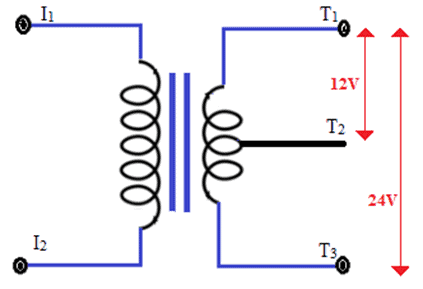
A 12-0-12 transformer is a step-down center-tapped transformer with an input voltage of 220V AC at 50Hz and an output voltage of 24V or 12V (RMS). It is named 12-0-12 transformer because of the output potentials of the three terminals as shown in the figure above. The secondary winding consists of three terminals: the two terminals for end to end and a third terminal as the center tap. In the figure above, the voltage will be 24V across the end to end (T1 and T3). Across the T1 and T2, the voltage will be 12V. The 0 in 12-0-12 represents the reference point with 0 voltage.
Thanks for reading! Leave a comment below if you have questions about anything…

Will anyone know what you are talking about? A transformer consists of the following parts:
Primary coil
Secondary coil
Core
Insulating materials
Transformer oil
Conservator
Breather
Tap changer
Cooling tubes
Buchholz Relay
Explosion vent
If I see this description of a transformer, I would expect to see a big lump of metal about 4meters x 4meters x 4 meters with a power station close by. A bit difficult to put into an electronic circuit! Keep things simple instead of copying from sources on the internet. This section needs a complete re write to make sense to any budding electronics student.
Is the first equation for the relationship of the input and output current and the coil wraps of the transformer correct?
It appears to be different (the reciprocal) of the equation used in the later section for “Determining the VA and Calculating the Max Current for Primary and Secondary Windings”
There is so much wrong with this article it’s difficult to know where to start. Does anyone peer-review the material before it’s published? Does anyone check that each statement is always true, and that each statement/section makes sense from the previous?
The email announcement of this page said “Learn how to setup an SD card reader on the Arduino, and how to save sensor data to a file on an SD card.” – not so important, but another indication of the lack of checking. (same text on https://www.circuitbasics.com/diy-electronics)
Buchholz Relay? – what’s the point of mentioning it with no explanation? Several other terms are like that.
“The number of turns of the coil should be a multiple of the number of turns in the secondary coil.” – not true, e.g. 240V to 13V, or 240V to 500V.
“It is used to control the voltage levels between circuits” – that’s a strange way of stating it, not exactly wrong, but confusing.
“Coil Wire Wraps and Output Voltage and Current”
– Why start calling them Wraps? when everywhere else they are called turns
– Why isn’t the equation given as ‘Secondary Voltage =
– There’s no mention of Current in this section despite the title.
It gives the impression that the article has been cobbled together from sections of others without any real understanding.
I talk to young people about programming and electronics and it would be good to point them at a site like this, but this page would not help them.
I am interested in transformers. I have some questions that even if they are to difficult to breifly and CLEARLY answer, a reference that deals with the subject would be appreciated,
QUESTION_1
A center tapped winding can NOT divide the total voltage of both windings PRECISELY equally due to differences in the core coupling different amounts of flux to each winding.
What is the typical difference to be expected between the 2 voltages ?
QUESTION_2
Suppose the secondary is bifilar wound . In theory the voltage difference between the 2 windings would be ZERO.
In practise the flux coupling to each winding still has minor differences in spite of bifillar winding and probably would be far
better if a toroidal core were used.
Can you give a rough estimate as to the NEW (small) voltage difference that bifilar windings might produce ?
j
It was interesting when you talked about how the number of wraps in the secondary coil affects the voltage caused by the current. My uncle is looking for an electrical engineering service to provide testing on the components of his new industrial plant by the highway. Asking about the specifics of transformer voltage should help him find an electrical engineer that’s experienced and reliable.
Your formula is incorrect. regarding the current and voltage with the coil turn ratio. You say output current and output voltage have an inverse relationship (which is true), but they both equal the same ratio. This is probably a mistake, but it should be fixed