In this tutorial, we are going to send sensor data to a web server and display it on a webpage using the Arduino UNO and an Ethernet shield.

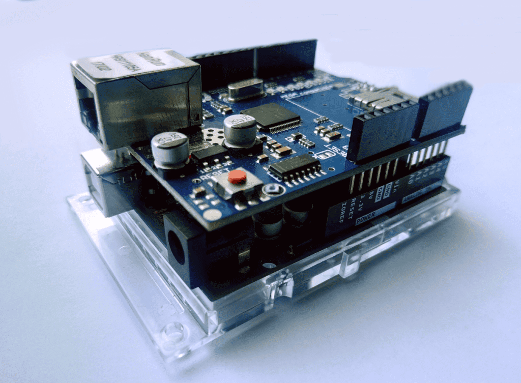
Arduino Ethernet Shield
Just for the record, the Arduino alone cannot function as a web server. Unlike the Raspberry Pi, which is a fully-functioning computer, Arduino requires an Ethernet shield to connect to the internet.
The Arduino Ethernet shield is a circuit-printed board that allows an Arduino to connect to the internet. It is based on the Wiznet W5xxx line of Ethernet chips. These chips have a network stack capable of both TCP and UDP. However, the shield only allows wired connection via the RJ45 connector. So if you’re looking for a wireless internet solution, you might want to look at an ESP8266 board instead. The Arduino Ethernet shield has an integrated microSD card reader, which you can use to store files for your webpage.
You can still interface with most of the Arduino’s pins using the female header pins of the Ethernet shield. Simply line up the pins of the shield and Arduino and press them down until they’re in a comfortable fit. The pins you cannot use are pins 10 (SS), 11 (MOSI), 12 (MISO), and 13 (SCK). These are SPI pins, which the Arduino uses to communicate with the Ethernet shield.
Building the Project
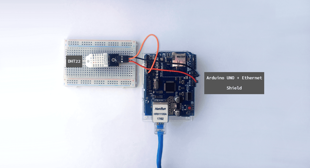
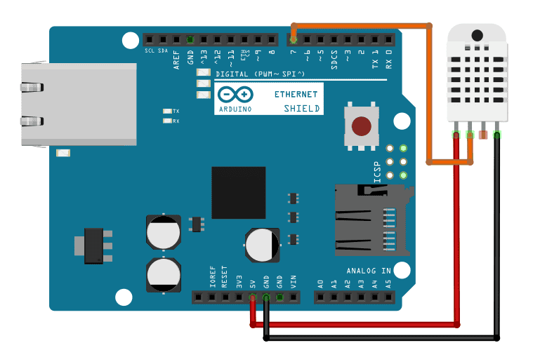
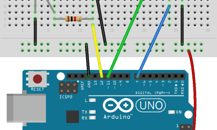
For this project, we are going to display DHT22 temperature and humidity sensor data from an Arduino and an Ethernet shield paired to a web page you can access anywhere in the world. To accomplish that, connect the following components, as shown in Figure 2:
To learn more about the Arduino, check out our Ultimate Guide to the Arduino video course. We teach Arduino programming and circuit building techniques that will prepare you to build any project.
After assembling the components, plug a LAN cable to the RJ45 connector. The other end must be on your router that is connected to the internet.
The Code
Once you have connected all of the parts, upload this code to the Arduino:
#include "DHT.h"
#include <SPI.h>
#include <Ethernet.h>
#define DHTPIN 7
#define DHTTYPE DHT22

DHT dht(DHTPIN, DHTTYPE);
byte mac[] = {
               0xDE, 0xAD, 0xBE, 0xEF, 0xFE, 0xED
             };

IPAddress ip(192, 168, 1, 99);
EthernetServer server(80);

void setup()
{
  Serial.begin (9600);
  dht.begin( );
  Ethernet.begin(mac, ip);
  server.begin( );
}

void loop( )
{
  float h = dht.readHumidity( );
  float t = dht.readTemperature( );
  EthernetClient client = server.available();
  if (client)
    {
      boolean currentLineIsBlank = true;
      while (client.connected ( ) )
        {
          if (client.available ( ) )
            {
              char character = client.read ( );
              Serial.write(character);
              if (character == '\n' && currentLineIsBlank)
                {
                  client.println ("HTTP/1.1 200 OK");
                  client.println ("Content-Type: text/html");
                  client.println ("Connection: close");
                  client.println ("Refresh: 5");
                  client.println ( );
                  client.println ("<!DOCTYPE HTML>");
                  client.println ("<html>");
                  client.print ("<Title>Arduino Ethernet Webserver </Title>");
                  client.print ("<h1>Arduino Ethernet Shield Webserver </h1>");
                  client.print ("<h4>Temperature in C: ");
                  client.print (t);client.print("C");
                  client.print ("</h4><h4>Humidity: ");
                  client.print (h);client.print("%");
                  client.println ("<br />");
                  client.println ("</html>");
                  break;
                }

                if ( character == '\n')
                  {
                    currentLineIsBlank = true;
                  }
                else if (character != '\r')
                  {
                    currentLineIsBlank = false;
            }
        }
    }
    delay(1);
    client.stop();
  }
}
Code Explanation
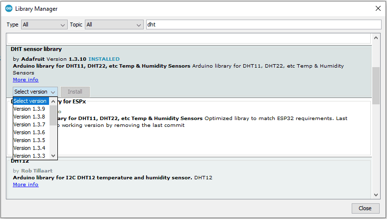
First, we need to include the required libraries. We will use SPI.h and Ethernet.h to communicate with the Ethernet shield. Both are already available in the Arduino core library so no need to install. Additionally, we will use DHT.h to interface with the sensor. You can download it here. Alternatively, you can go to Tools > Manage Libraries, and get the DHT library there.
The DHT library requires the code to specify the pin where the sensor is connected and the type of sensor you’re using. In our case, we set it up to pin 7 and used a DHT22.
Next, we define the MAC address of the shield. The MAC address in the code is the default address for this type of shield. So if you’re using the same as mine, leave them as is. If you’re not confident, check your shield for a sticker with your MAC address. It’s usually on the bottom side.
Next, we use IPAddress ip(192, 168, 1, 99) and EthernetServer server(80) to establish a web server at port 80 with a static IP address of “192.168.1.99”. If you want to use a different IP, just change the values from that variable. Be sure to use an unused IP address or else you’ll encounter networking problems.
In the loop function, we read the data from DHT sensor using readTemperature() and readHumidity(). Then using print(), we send the HTML commands to the client.
Demonstration
Visit the static IP address (192.168.1.99) you set in the code in any web browser inside your network. It should show this and should update every 5 seconds as indicated in this line from the code: client.println ("Refresh: 5").

Port Forwarding
Finally, in order to make the server available outside your home network so that you can access it anywhere, we need to employ port forwarding.
Port forwarding is a network router feature that directs traffic from a particular port in your WAN to a device inside your LAN. Here’s how to do it:
1. First, find your WAN IP address. You can do this by searching Google for “what is my IP address”.
2. Then, visit your router’s homepage. Enter your router’s gateway IP address in your web browser. Every model varies. For instance, my Hitron Technologies router uses “192.168.0.1”. On the home page, log in.
3. Next, explore the interface. Find out how to change the DHCP settings. Add the ESP-01’s IP Address to static so that it remains fixed. For our example server above, that would be “192.168.0.18”. Also, enter the MAC address you got from the AT+CIFSR command. After applying these, your router then reserves the 192.168.0.18 address to the ESP-01.
4. Next, go to the Port Forwarding settings. Create a virtual server using the TCP protocol. Use port 80 then enter the ESP-01’s IP address. Don’t forget to save the changes you’ve made to your router.
5. Last but not the least, configure your Firewall Settings to allow port 80 to communicate directly with your devices.
Thanks for reading! Let us know if you have questions about anything in the comments section below…


DISPLAY SENSOR DATA WITH AN ETHERNET CONNECTED ARDUINO WEB SERVER – Will this work with the Arduino Ethernet Shield 2?
Yes, both work with the Arduino Ethernet library.
how would you do this with a wifi shield?
I’ll use Arduino’s built-in WiFi library instead of Ethernet.h, then create a web client and print the HTML commands directly, just like the code above.
What about using with an arduino Teensy? Do you have a connection guide for the Teensy?
I haven’t tried a Teensy yet but a quick google search shows they have ethernet adapters as well. You can use this library: https://github.com/PaulStoffregen/Ethernet. It’s practically the same with the one used here but for Teensy boards.