No, this article is not about gardening! The words ground and earth are so common and mean different things to different people. But in this article we are referring to electrical grounds.

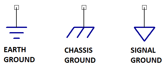
When doing electronic design, ground, earth, and chassis are important concepts. All three imply a point of theoretical zero volts, but this may not always be true or even possible. There are also differences in the schematic symbols, as shown below:
Definition of Terms
- Earth ground: The point where the grounding system will run to the planet. This can be achieved with a copper rod hammered into the soil or a connection to a water pipe (ideally copper). Places that rely on good earth (telephone exchanges, radio stations, power stations) often bury large pieces of copper mesh or copper plates. In the case of transmitters, radials can be buried underground. Lightning protection also requires not only a good ground but substantial current carrying capacity.
- Chassis ground: In a system like a computer or radio, it is impractical to connect common 0V points to the earth ground, so these connect to the chassis, casing, or housing of the device. Ideally there is only one common point. In devices with a danger of shock, for example a kettle or toaster, the housing will also be connected to mains earth. This means that in the event of a broken live wire touching the housing the current will be shunted to earth and hopefully trip a circuit breaker before anyone gets shocked.
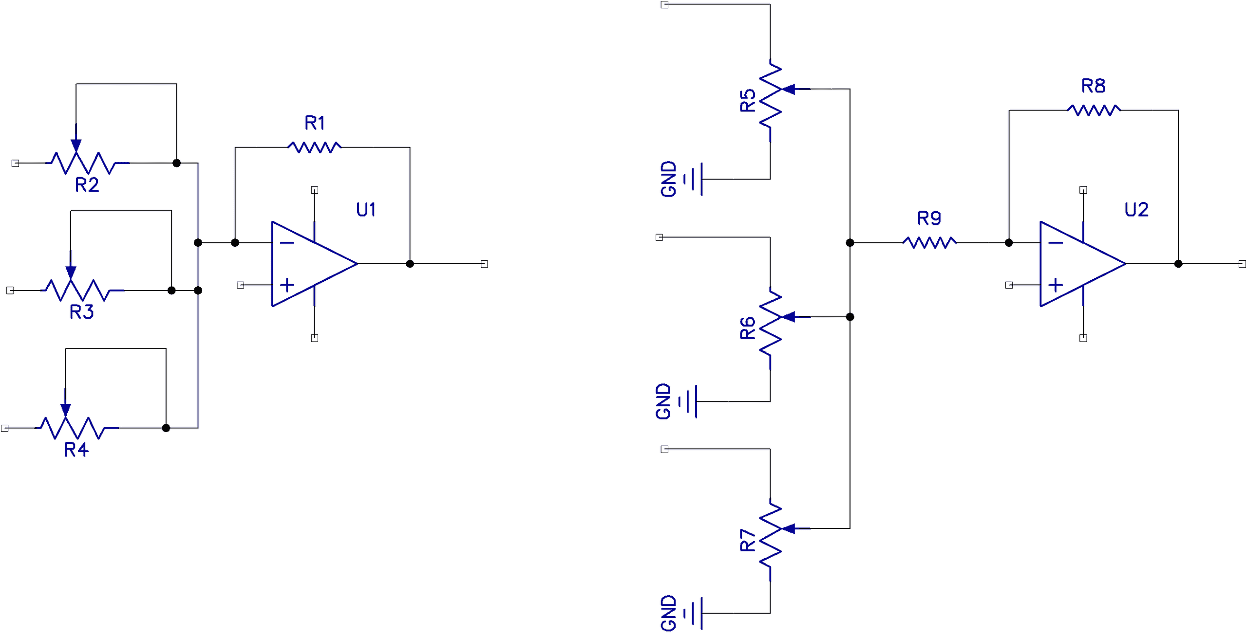
- Virtual ground: This is a point on a circuit that cannot be used as a ground but behaves like a ground point. For example, an inverting op-amp has a virtual ground at the -ve pin.
- Floating ground: Used in devices where the power supply is isolated from the mains by a transformer, or where the device is portable and running off its own battery. For example, the circuits in a cell phone use a floating ground. Also, mains powered devices with only two pins (like a hairdryer) also use floating grounds.
- Signal ground: In an electronic system such as an amplifier, there are many points where components are to be connected to zero volts. Because the system may have substantial amplification and, in some places, large currents, tiny voltages can be set up in the ground tracks, which will cause oscillation. In RF systems, a ground plane or large area of copper in one of the PCB sides can help screen parts from each other. Check out this article for more info on ground layouts: How to Design a PCB Layout.
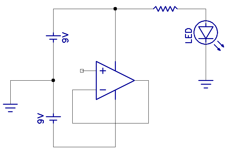
In the circuit below, two 9V batteries are connected in series, and the common point is connected to create a ground. This effectively creates a dual supply rail with positive and negative voltages (+9V and -9V), which could be used to power an op-amp:
Common Grounding Problems
We hope that all grounds and earth sit at a theoretical zero voltage, but this is never quite true.
On a ship, for example, there may be a potential difference of tens of volts between ‘grounds’ on different decks or parts of the ship. Someone using a long extension cable notices significant voltages between the deck where he is working and the earth on the extension cord. A similar problem occurs on aircraft surfaces as they cut through the earth’s magnetic field at super high speeds. This creates a small potential difference between the ground points.
Conductors, wiring, joints, and even the soil itself has impedance, so as current flows through the material, a voltage is generated.
Where possible, circuit designers strive to avoid loops and multiple earth loops and bring all grounded points back to one common point. This is often the point where the power supply enters, or where the main smoothing/decoupling capacitors are connected to the chassis.
In systems with high gains, such as amplifiers, large currents will be present in the ground wiring. It becomes paramount to see that these grounds are not shared with the input stages of the amplifier. Otherwise, oscillation is inevitable. The input and output stages should only meet at a common star ground.
Ground Loops
Ground loops are a problem in high gain audio systems when connecting devices with separate mains power supplies. For example, a mixing board is connected to a PA system, and each has its own mains power supply. The metal grounding screen inside the audio cables can form a loop with the different mains earths, causing substantial hum problems.
In a mains power supply system that is a three-phase system, the neutral point is supposed to have zero potential when the loads on each phase are balanced. This is seldom the case. Large currents on one phase will cause the neutral to ‘float’ up, causing voltage fluctuations on the other phases. For this reason, the neutral is taken to earth with good quality earth such as a grounding rod.
In many countries, the neutral point is also earthed at the consumer’s supply entry point.
Earth Leakage Relays
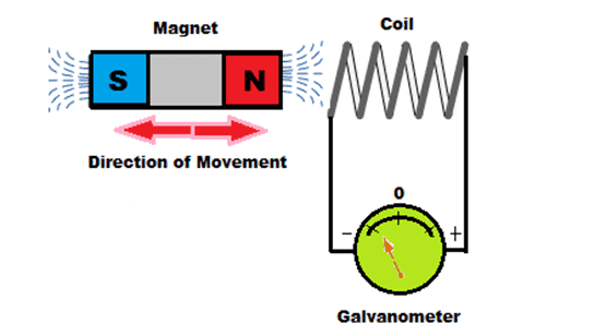
Earth leakage relays have two coil windings going in opposite directions. The live and neutral mains wires are fed through these windings. Because the outgoing and incoming currents are the same, there is no flux in the relay coil, and it does not operate. However, in the event of a leakage fault – something/someone gets connected between live and earth, the returning current will be less, as it is now flowing to earth, and the relay will operate, disconnecting the supply.
Note that an earth leakage relay cannot protect you if you contact a live and neutral wire at the same time. In this case, the earth leakage relay thinks you are a light bulb and will make you light up!
Many electronic components, like MOSFETs and CMOS chips, can be damaged in handling and transport. Assemblers are often wear wrist grounding straps and a partially conducting work mat or floor mat (carbon impregnated). Note that wrist and ankle straps must go to earth via a 1M resistor to prevent shock in case of accidental mains contact.
A lightning protection system also presents an RF type problem in the case of a high building. Even with substantial current-carrying and, thus, low resistance copper wire/strap, the rise time of lightning is very high, behaving like an RF pulse. The inductance of the long wire will cause substantial voltages to appear across it.
Hope this guide has helped you understand electrical grounds and grounding. Leave a comment below if you have questions about anything!

Thanks for that. What is the situation with garden pond pumps? These are often mains voltage and are submerged. The pond water is isolated from ‘earth’ by the rubber or plastic pond liner. If the pump’s live parts ever come into contact with the water, would it be dangerous for anyone touching the water while also in contact with the surrounding ground?
Please contact a licensed electrician. The pump should have special safety equipment and be designed for this use. There are also specific devices called ground fault circuit interruptors which may be required. In north America there are specific electrical codes (NEC) and standards (UL Listing) that address these issues. Only use pumps specifically designed and Listed for this purpose. The licensed electrician can advise on your specific conditions. This can be a serious life safety issue!
Hi,
In the “Common problems” paragraph Ohms’s law formula is faulty. Should be written V=R x I.
Thanks for catching that! We’ve just changed it to V=IR.
Dear sir good day;
I would like to know why do we use the minus (-) voltage in some circuits .
I was wandering when I bought a power supply minus 63 volt wrongly and since that time I was trying to find out the reason of using minus voltage in place of plus voltage in everywhere.
Many thanks in advance.