In this tutorial, we will use a 74HC165 (PISO) shift register to synthesize a low-frequency sine wave that can generate oscillating voltages on the seconds to minutes time scale. An understanding of some bitwise Arduino manipulation will prove helpful for this project. You can check some of that out here. We also have another article that goes more in-depth into how to use shift registers on the Arduino.

How Shift Registers Work
Before we begin this project, we should get some background information on shift registers.
The heart of a shift register is based on a flip flop. A flip flop is a memory cell or bistable that can exist in two states, either a 1 or a 0. Once you set it to a certain state, it retains it as that until a further clock pulse sets it into a different state. A shift register is made up of several flip flops connected together in different ways depending on the purpose.
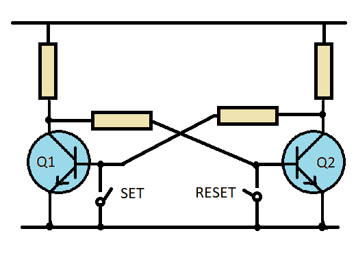
Figure 1 shows two transistors that are cross wired so that if a low is sent to the base of Q1 via the set switch, it turns off, causing its collector to go high which forces Q2 into an ‘on’ state. As the collector of Q2 becomes low, it will reinforce the low on Q1 base. This state will remain static until a second ground pulse arrives at the base of Q2 “flipping” it off again and the Q1 on, hence called flip flop. Of course, there should be additional steering logic to make this functional. This is also known as a bistable multivibrator. For the early shift registers mentioned above, the two transistors would have been triode valves.
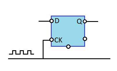
In Figure 2, we see a real logic gate flip-flop that has a data pin where it reads the data as either a 0 or a 1, and a clock pin which will clock that data state into the flip flop causing it to become available on the output pin (usually called Q).
This D-type flip flop is a commonly used type of flip flop (4042, 4013, 7473). Every time a clock pulse arrives, it will copy the state of whatever is on pin D to pin Q.
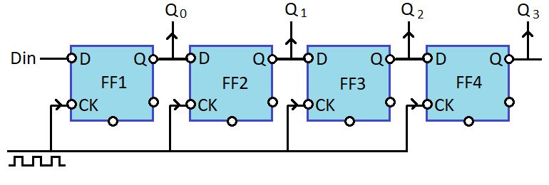
Figure 3 shows the basis of a Series In Parallel Out (SIPO) shift register. It is a chain of D-type flip flops, thus the output of each feeds the input of the next. Because they are all clocked together at the same time, the state of the input at D1 will clock or move along until it emerges at the last Q output. While this is going on, a parallel version of this data is being presented at all the Q outputs as a nibble (a nibble is half a byte).
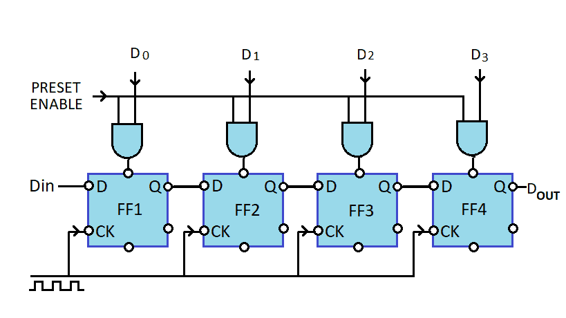
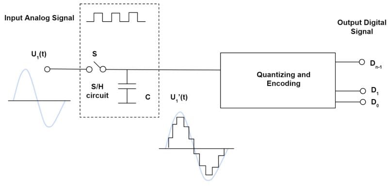
Figure 4 shows a Parallel in Serial Out (PISO) shift register. Here, a parallel nibble is loaded via a preset enable pulse into the flip flops. Again, the clock signal consistently marches them out to the end resulting in a parallel-to-series conversion. Both a PISO and a SIPO would make the basis for a communications channel if the serial in and the serial out were connected to each other. As each flip flop needs two clock half cycles to change it, it is effectively dividing by two (remember when we discussed shift right and shift left >> << in the bitwise tutorial). So in the figure above, as each flip flop divides by two and we have 4, then this circuit will divide by 16.
The Sine Wave Generator
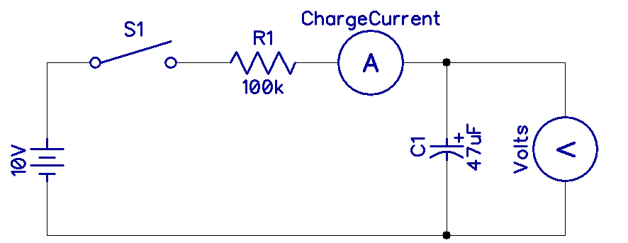
Creating sine, triangle and square wave oscillators is usually done with oscillators using a resistor and capacitor as the timing elements. This works well at audio and higher frequencies. When you want something a lot lower, i.e. to design a sea wave generator for your pool and you wanted a frequency of less than 1Hz maybe even 1/10 of a Hz, you would end up with very large capacitor values (big and expensive) in the RC circuit.
The circuit below is very stable as it is not dependent on any RC values and the frequency is only proportional to the clock frequency. In the example, this was derived from an Arduino so it is accurate and it is usually better than 1 part in 106.
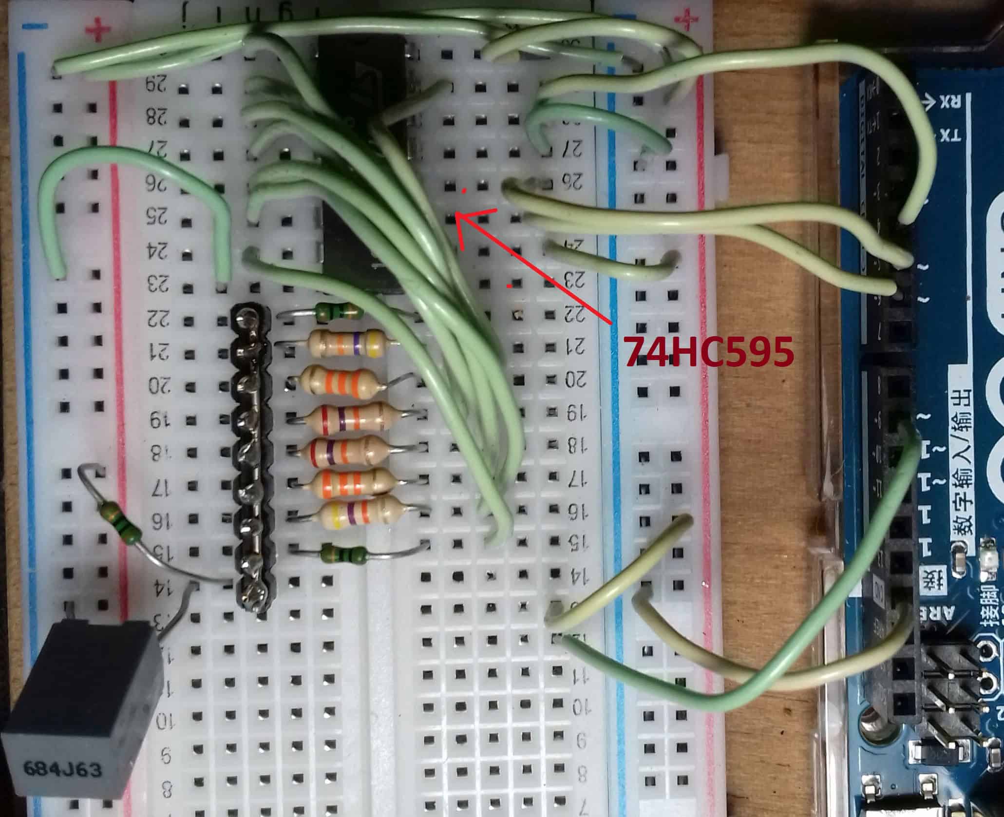
Building the Sine Wave Generator
These are the parts you will need to build the sine wave generator:
- Arduino Uno
- Jumper wires
- Breadboard
- 74HC595 PISO shift register
- Resistors: 10K (1X), 27K (2X), 33K (2X), 47K (3X), 100K (2X)
- Capacitors: 0.1 uF (1X), 0.47 uF (1X)
- Barrel power jack
To learn more about the Arduino, check out our Ultimate Guide to the Arduino video course. We teach Arduino programming and circuit building techniques that will prepare you to build any project.
How the Sine Wave Generator Works
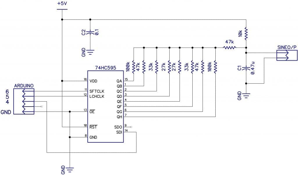
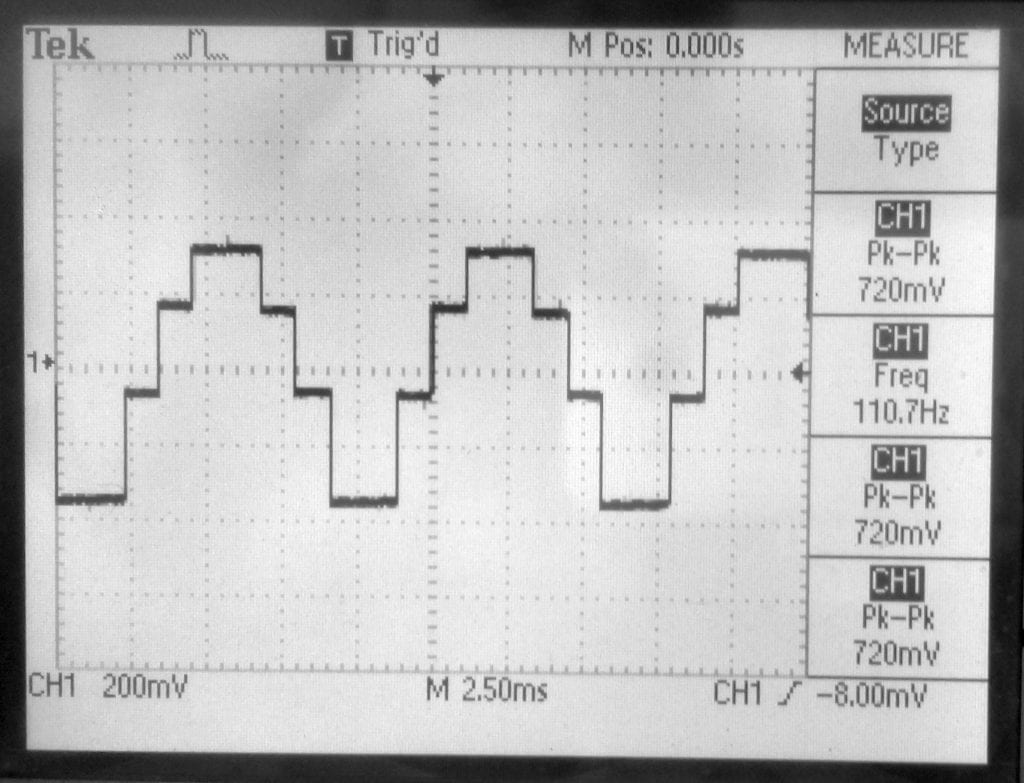
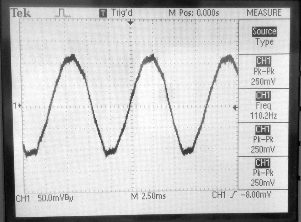
So how does it work? A low bit is clocked through the 8-bit shift register. As each Q output goes low, it draws current through the resistor on that pin forming a potential divider and producing a voltage which is dependent on the value of the resistor. If these are calculated correctly, they form a point on a sine wave curve. Since there are only eight (8) points in the illustration below (see figure 7.1), it looks a bit rough. But if we add a capacitor (or better still a proper low pass filter), the square harmonics are removed creating a plausible low frequency sine wave. Here is a website showing the formula for calculating the resistors if you wanted to use all 16 bits.
Application and Testing
This set up was able to generate frequency stable sine waves at below 1Hz. If you want to go further, use all 16 bits of the 74HC595 and a decent two-stage low pass filter. This creates a sine wave with 1/16 steps. The raw wave form has only 6% distortion but with the filter, it will be very much better at 1%. In this circuit with eight (8) steps and a simple capacitor, the distortion was only 6%.
Thanks for reading and be sure to leave a comment below if you have questions about anything!

Don Lancaster’s “CMOS Cookbook” has a few pages on using walking ring counters with a resistance ladder to generate a sine wave. Five flip flops to generate an eight bit waveform. You can read about it on google books.
https://www.google.com/books/edition/CMOS_Cookbook/PhW9eMDmFGYC?hl=en&gbpv=1&dq=cmos+cookbook+sine+wave&pg=PA384&printsec=frontcover