Electret microphones are excellent at detecting sound. You can take advantage of electret microphones to build Raspberry Pi projects that can detect sound and do something when it does detect a sound.

In this tutorial, we will connect an electret microphone to the Raspberry Pi and turn on a 5V relay when a particular sound level is reached.
How Electret Microphones Work
An electret microphone consists of a diaphragm, a pair of electrodes, and a transistor. The diaphragm responds to to changes the air pressure generated by sound waves. This causes a change in capacitance between the diaphragm and a charged metal plate inside the microphone housing. The varying capacitance produces a modulating voltage, which is amplified by a JFET transistor inside the housing. This creates a small sinusoidal voltage signal at the microphone pins that depends on the air pressure generated by sound waves.
To detect the signal from an electret microphone on a microcontroller or single-board computer, we need to use a comparator to convert the analog signal into a digital signal.
The KY038 Microphone Breakout
Fortunately, there is the KY038 microphone breakout. This breakout board has built-in comparators, potentiometers, and a preamplifier to make it easier to connect to the Raspberry Pi:
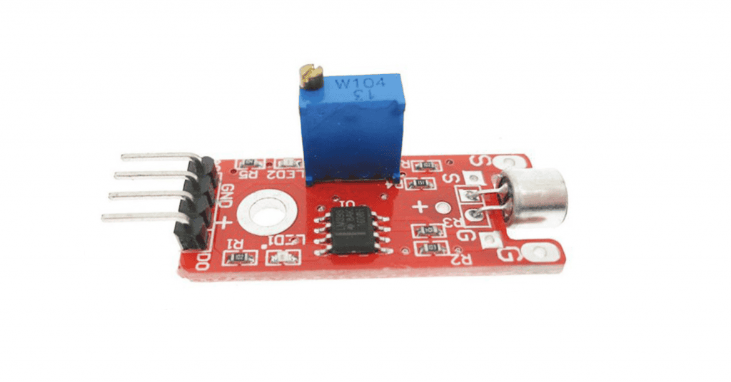
The digital output of the KY038 is high whenever a particular sound level threshold is reached. You can set the threshold using the onboard potentiometer. The analog output of the KY038 is the unamplified signal from the electret microphone. You can use this unaltered signal to drive a speaker if you send it to an amplifier first.
The KY038 is perfect for detecting when a door closes, controlling devices using hand claps, and noise level monitoring.
Using the KY038 Microphone Breakout with a Raspberry Pi
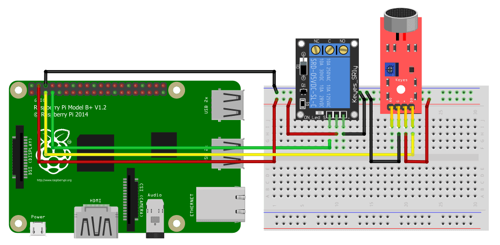
To demonstrate how to use the KY038 with a Raspberry Pi, we will build a circuit that triggers a 5V relay when a certain sound threshold is detected by the KY038 microphone.
These are the parts you will need:
Connect the devices according to the wiring diagram below.
Code
Next, open up your favorite code editor on the Raspberry Pi and copy the code below.
import RPi.GPIO as GPIO

MicPin = 3
RelayPin = 4

GPIO.setwarnings(False)
GPIO.setmode(GPIO.BCM)

GPIO.setup(MicPin, GPIO.IN, pull_up_down=GPIO.PUD_DOWN)
GPIO.setup(RelayPin, GPIO.OUT, initial=GPIO.LOW)

while True:
    GPIO.output(LedPin, GPIO.input(MicPin))
The code starts by importing the Rpi.GPIO library. We rename it GPIO for ease of use. We then declare the microphone and relay pin numbers and set them to input and output, respectively. We need to declare the pin with a pull-down resistor for the signal to stay LOW for input devices.
The main loop works such that whenever the input from the sound sensor returns HIGH, it will also write HIGH to the relay, triggering whatever device the relay is connected to.
Thanks for reading and be sure to leave a comment below if you have questions about anything!

Hi there,
Would it be possible to use a line in audio tone instead of the electret mic? Would the KY038 still work or is there another board you’d recommend?
Thanks in advance!
LedPin was not declared… did you mean RelayPin in the last line of your code?