An electrical schematic is a diagram that shows how all of the wires and components in an electronic circuit are connected. They’re like a map for building or troubleshooting circuits, and can tell you almost everything you need to know to understand how a circuit works.

The ability to read electrical schematics is a really useful skill to have. To start developing your schematic reading abilities, it’s important to memorize the most common schematic symbols. Each physical component (i.e resistor, capacitor, transistor) has a unique schematic symbol. The main goal of this tutorial is to show you the essential schematic components you should know.
It’s not enough to just be able to recognize the components in a schematic. You should also be able to get a rough idea of how the circuit works, just by looking at the schematic. After this article, I recommend reading How to Analyze Circuits, where we discuss more advanced circuit analysis techniques like Kirchhoff’s Current Law and Kirchhoff’s Voltage Law.
POWER SOURCES
Power sources supply electrical energy to a circuit in the form of voltage and current. Every functional electronic circuit needs to have a DC or AC power source.
DC Power Sources
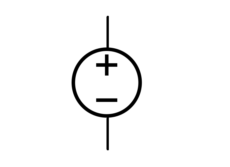
Direct current (DC) power sources provide electric current that flows in a constant direction. This is the schematic symbol for a DC power source:
AC Power Sources
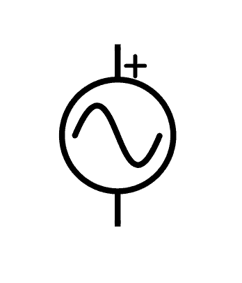
Alternating current (AC) power sources provide electric current that flows in two directions. This is the schematic symbol for an AC power source:
Batteries
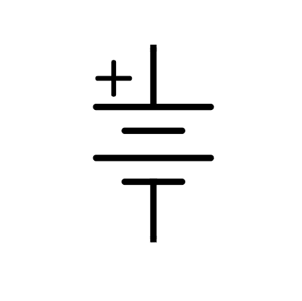
A battery is a common type of DC power source. The schematic symbol for a battery is made up of short and long parallel lines. The longer line represents the positive terminal of the battery, while the shorter line represents the negative terminal:
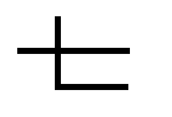
Ground
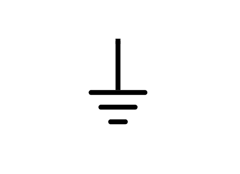
Ground is the common return path of a circuit, where current returns to its source. This is often referred to as the negative side in a circuit. This is the schematic symbol for a ground connection:
Terminals
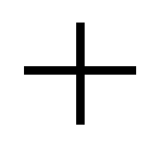
Terminals are connection points to external circuits. For external connections, terminals are denoted by empty circles:
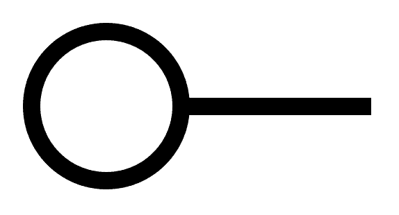
Terminal connections are different from nodes or junctions which have solid circles:

Switches
Switches make or break a connection in a circuit. They also let you change the path of current flow.
SPST Switches
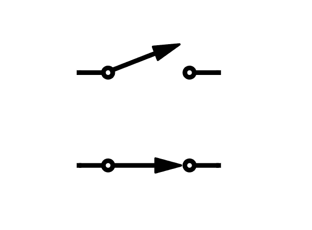
A SPST (single pole, single throw) switch is an on and off switch. The two schematic symbols below show the different states of an SPST switch. The top symbol indicates that the switch is in the off position, which blocks the path of current. The bottom symbol indicates that the switch is on, which allows current to flow through the switch.
SPDT Switches
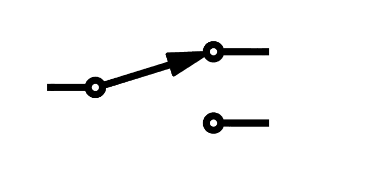
SPDT (single pole, double throw) switches can direct the path of current to different parts of a circuit. There are two routes for the current to flow in this switch, depending on the position of the switch:
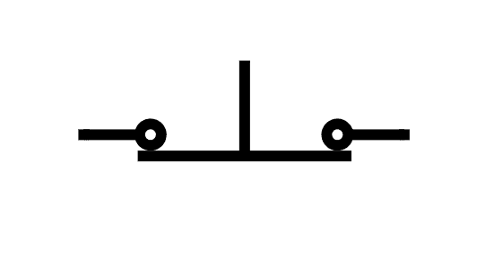
Momentary Switches
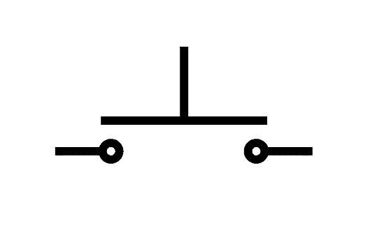
Momentary switches only remain open or closed while being pressed. Push button switches are the most common type of momentary switch. These switches are either normally open or normally closed. The top schematic symbol below shows a normally open push button switch in the open position, while the bottom symbol shows a normally closed push button switch in the closed position:
Multi-point Switches
Multi-point switches let you switch the path of an input current to multiple different output paths.
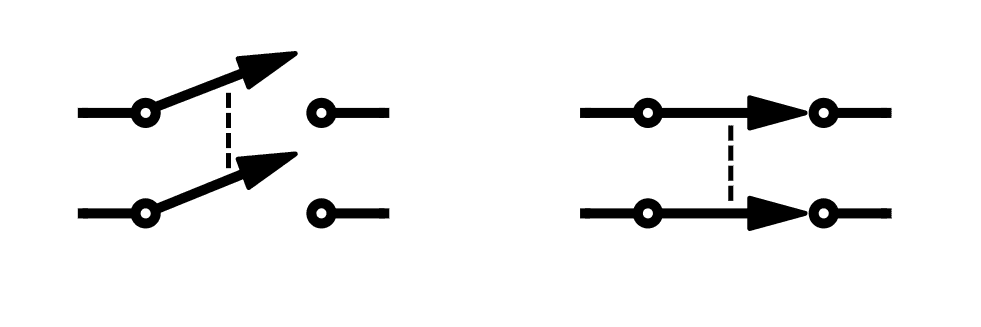
DPST (double pole, single throw) switches have 2 inputs and 2 outputs. These switches let you control the current flow to two outputs. Since the switches are single throw, the two output terminals will both be switched on and off at the same time. The schematic symbols below show an open DPST switch (left), and a closed DPST switch (right):
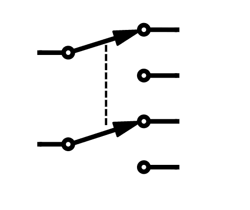
DPDT (double pole, double throw) switches have two terminals for input current and four terminals for output current. These switches let you switch the path of two input currents to four separate output paths. Here is the schematic symbol for a DPDT switch:
Resistors
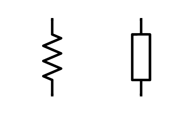
A resistor is one of the most basic passive circuit components. Resistors have electrical resistance, which restricts current flow. The schematic symbol for a resistor is shown below. The symbol on the left is the convention used in the United States, while the symbol on the right is the international standard:
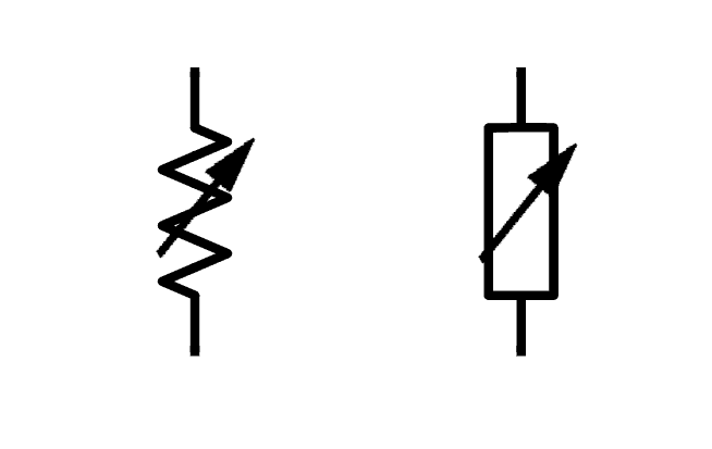
Variable Resistors
A variable resistor can increase or decrease its resistance depending on an external input. Analog sensors like photoresistors and thermistors are types of variable resistors because their resistance changes with varying levels of light or temperature. The schematic symbol of a variable resistor is similar to a fixed resistor, but a diagonal arrow is placed across the middle:
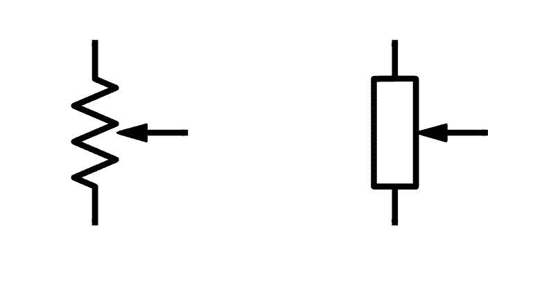
Potentiometers
A potentiometer is a three-terminal variable resistor that is used to adjust the voltage and current in a circuit. The two terminals of the resistor are V+ and ground. The arrow represents the potentiometer’s wiper, where the output voltage is taken from:
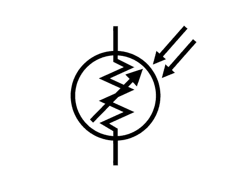
Photoresistors
Also known as light dependent resistors (LDR), photoresistors are light-sensitive variable resistors that change resistance with varying levels of light. This is the schematic symbol of a photoresistor:
Capacitors
Capacitors are passive electronics components that store electrical charge. There are two common types of capacitors – non-polarized and polarized.
Non-Polarized Capacitors
Non-polarized capacitors don’t have polarity, so it doesn’t matter which side is connected to positive and which side is connected to negative. These capacitors usually have smaller values than polarized capacitors:
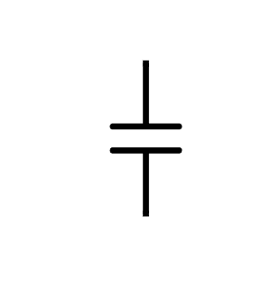
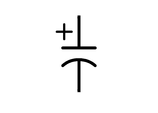
Polarized Capacitors
Polarized capacitors do have polarity, so it matters which side is connected to positive and which side is connected to ground. Polarized capacitors generally have higher capacitance values compared to non-polarized capacitors. Here’s the schematic symbol of a polarized capacitor:
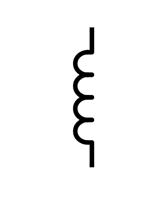
Inductors
Inductors are passive components that create a magnetic field when current flows through them. Inductors can be as simple as a coil of wire. The schematic symbol of an inductor looks similar to a coil:
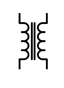
Transformers
Transformers are used to step up or step down voltages. They are made up of two wire coils wrapped around an iron core, so the schematic symbol has two coils with straight lines between them. The lines represent the iron core:
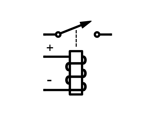
Relays
A relay is an electrically operated switch. Relays are basically electromagnets connected to an actuator that opens and closes a switch when current is applied to the coil:
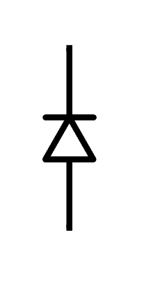
Diodes
A diode is a polarized device that only lets current flow in one direction. Being polarized, it has a positive lead (anode) and a negative lead (cathode). The flat edge of the triangle is the anode, while the line is the cathode:
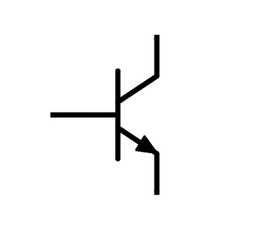
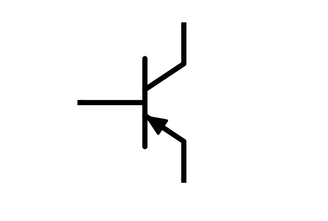
Transistors
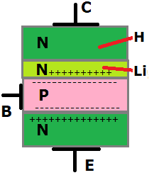
Transistors are used to either amplify voltage or to switch electric currents. The most common transistors are the bipolar junction transistors (BJT). There are two basic types of BJT transistors – NPN and PNP. NPN transistors turn on when current flows through the base of the transistor, while PNP transistors turn on when there is no current at the base of the transistor. The top schematic symbol shows an NPN transistor, while the bottom symbol shows a PNP transistor:
Integrated Circuits
Integrated circuits are circuits that contain hundreds to millions of resistors, capacitors, and transistors in a small package. Integrated circuits have many functions. There are integrated circuits for audio amplifiers, timers, microprocessors, and lots more. Three of the most commonly used integrated circuits are the 555 timer, the LM386 audio amplifier, and the LM358 operational amplifier.
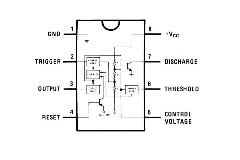
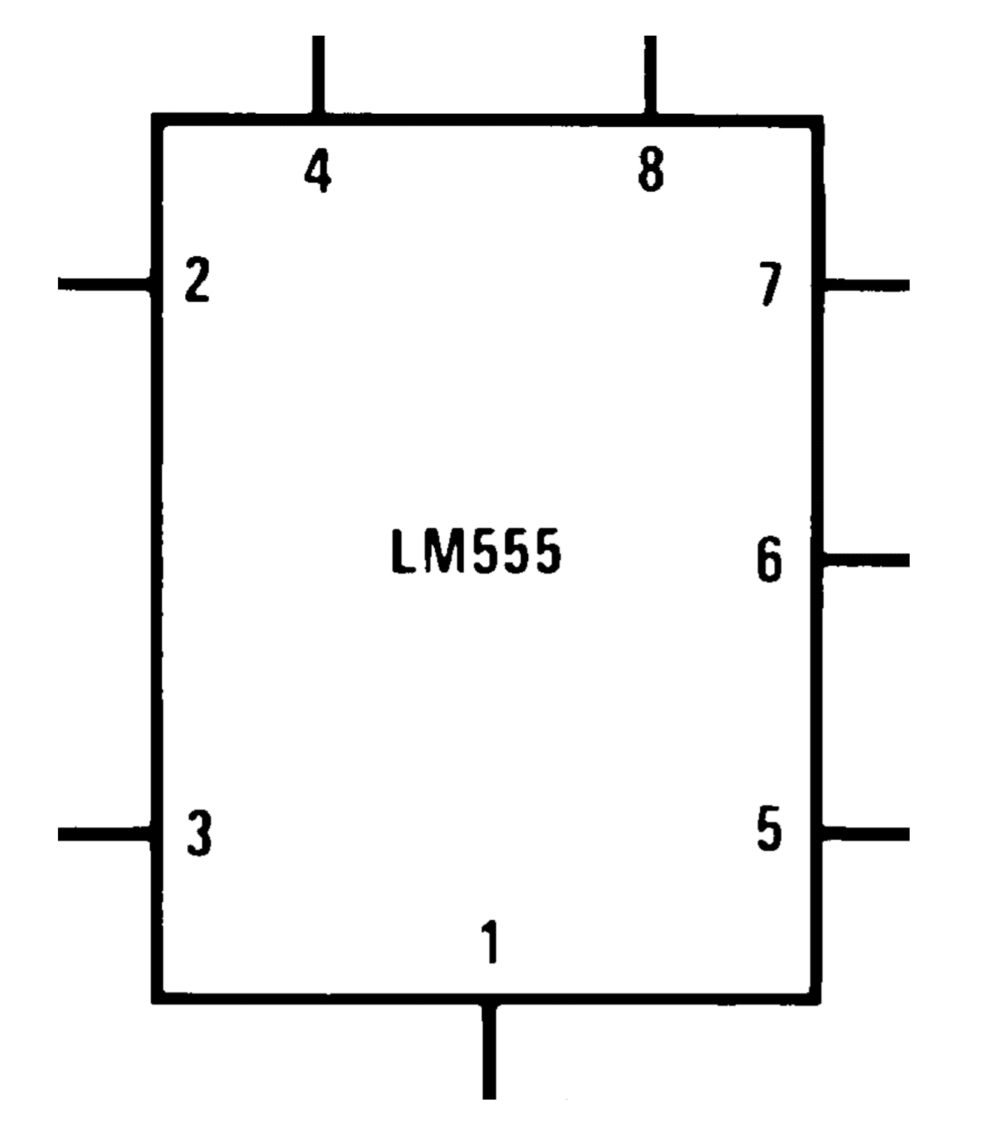
The 555 Timer
The most common use of the 555 timer is to provide timed electrical delays. However, it can also be used as an oscillator and as a flip-flop element. The diagram below shows the actual pin arrangement of the 555 timer with the internal schematic diagram of the IC:
The second image is the schematic symbol of the 555 timer used in diagrams:
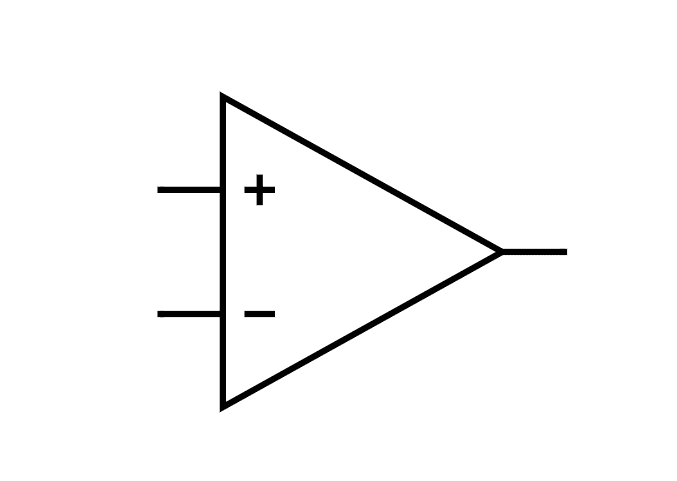
Operational Amplifiers
Operational amplifiers are voltage amplifiers with inputs and usually one output. They are also referred to as op-amps. The schematic symbol for an op-amp looks like this:
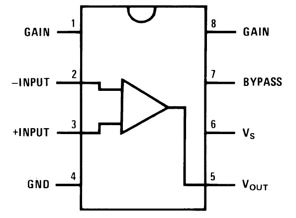
The LM386
The LM386 audio amplifier is an op-amp that is specifically designed for low power audio amplification. Being low powered, it’s perfect for battery powered audio devices like guitars, radios, and any other circuit that makes sound. Here is a pin diagram of the LM386:
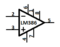
And this is the symbol used in schematic diagrams:
The LM358
The LM358 is a dual operational amplifier IC powered by a common power supply. Its commonly used as a transducer amplifier, integrator, differentiator, or voltage follower. Here is a pin diagram of the LM358:
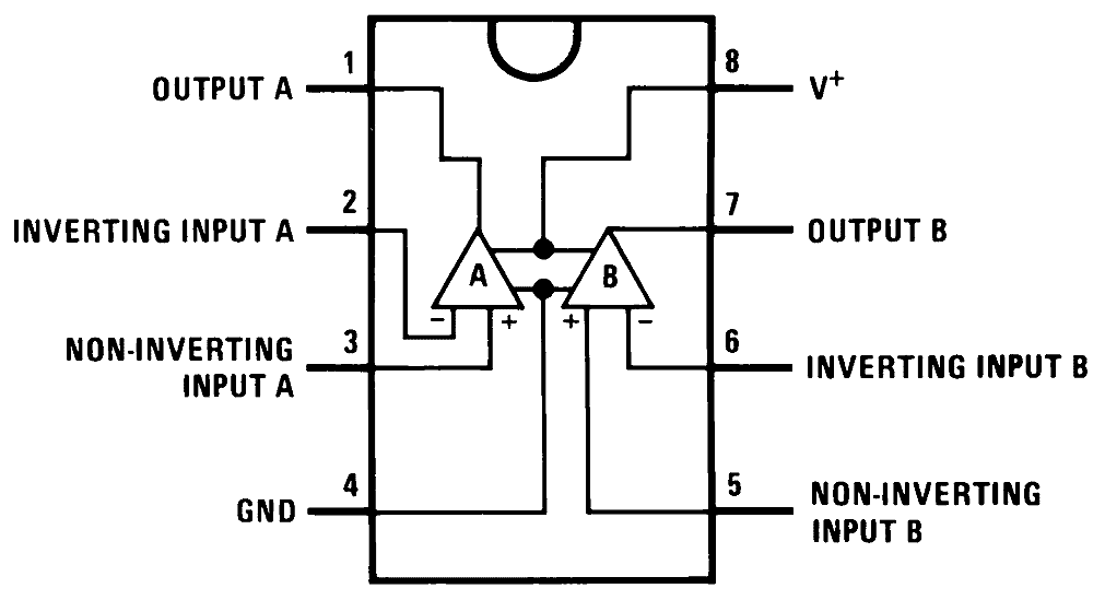
And here is the symbol used in schematic diagrams:
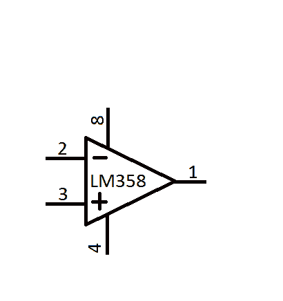
The schematic symbols for op-amps usually don’t show the pins that aren’t used in the circuit, as is the case for the LM358 symbol above where only five of the eight pins are shown.
Logic Gates
Logic gates are electronic circuits that process signals that represent true or false values. The four standard logic functions are AND, OR, NOT, and XOR. In addition to these functions, there are also NAND, NOR, and XNOR logic gates.
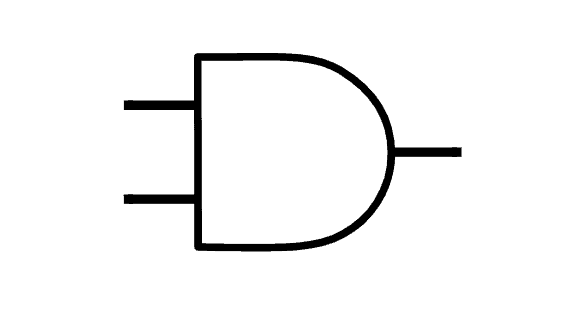
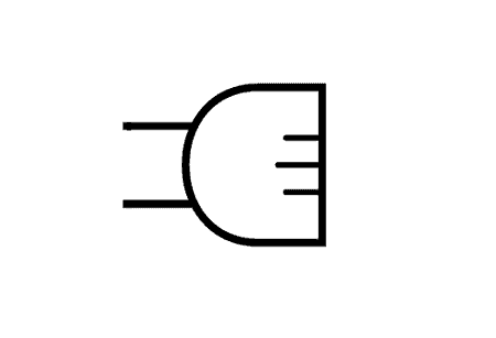
AND
The output of the AND gate is true when all of its inputs are true. Here’s the schematic symbol of an AND gate:
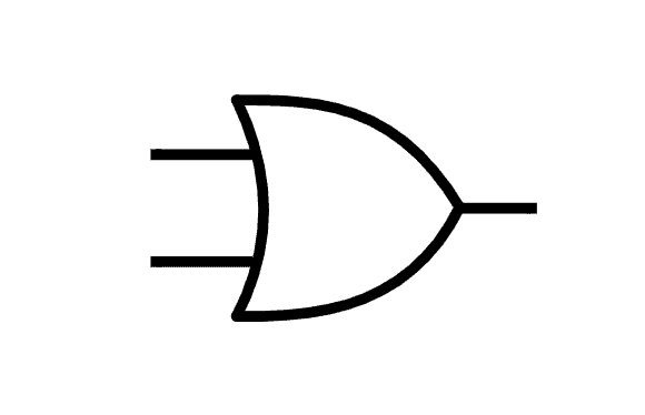
OR
The output of the OR gate is true when at least one of its inputs is true. Here’s the schematic symbol of an OR gate:
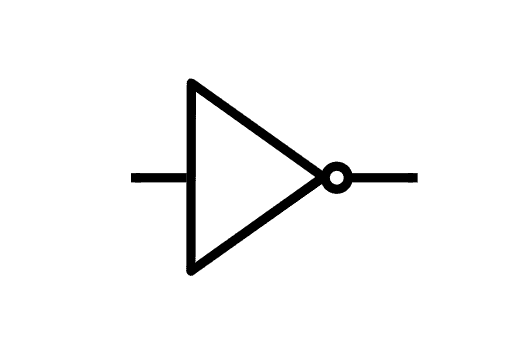
NOT
The NOT gate outputs the opposite of its input, which is why it’s also called an inverter. Therefore, the output is true when the input is false. Here’s the schematic symbol of a NOT gate:
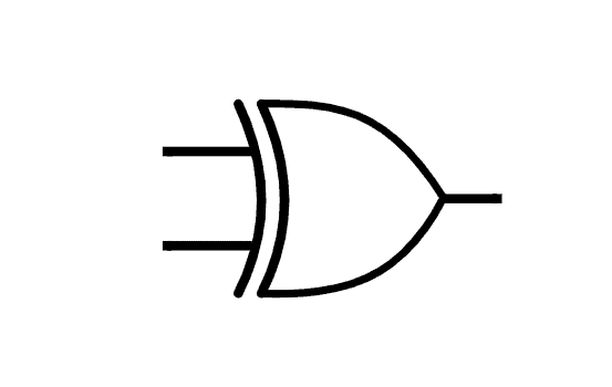
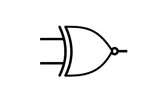
XOR
The “exclusive-OR”, or XOR gate has two inputs. The output of the XOR gate can only be true when one input is true and the other input is false. Here’s the schematic symbol of an XOR gate:
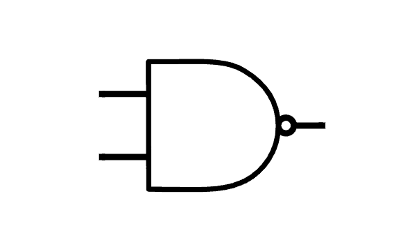
NAND
The “NOT-AND”, or NAND gate can have two or more inputs. The output of the NAND gate is true if any of the inputs are false. Here’s the schematic symbol of a NAND gate:
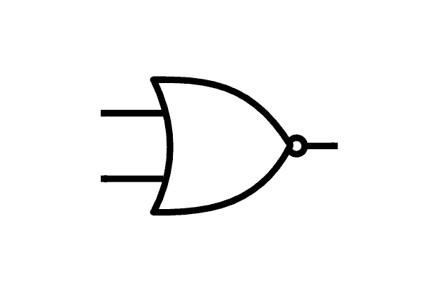
NOR
The “NOT-OR”, or NOR gate has two or more inputs. The output of the NOR gate is true when all of its inputs are false. Here’s the schematic symbol of a NOR gate:
XNOR
The “exclusive-NOR”, or XNOR gate has two inputs. The output of the XNOR gate is true only when both of its inputs are true, or when both of its inputs are false. Here’s the schematic symbol of an XNOR gate:
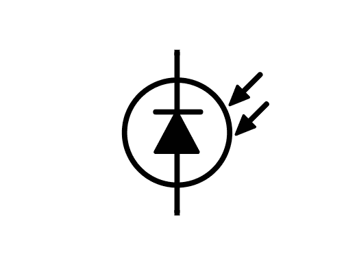
Optoelectronic Devices
Optoelectronic devices are devices that use light and electricity for various purposes. Optoelectronic devices can be divided into two categories – light-sensing and light-generating devices. For example, here is the schematic symbol for a light-sensing device called a photodiode:
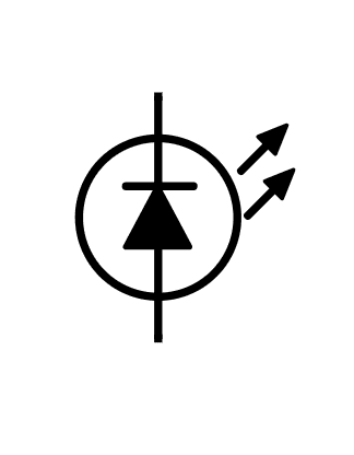
In contrast, here is the schematic symbol for a light-generating device called a light emitting diode (LED):
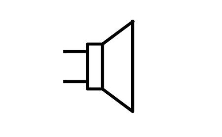
Speakers
A speaker converts electrical energy to sound energy. Its schematic symbol kind of looks like a real-life speaker:
Microphones
Microphones are a type of transducer that converts sound waves into an electrical signal. Here’s the schematic symbol of a microphone:
Fuses
Fuses are safety devices that provide over-current protection in an electrical circuit. The main element of a fuse is a narrow gauge wire that melts when there is too much current flowing through it. Here’s the schematic symbol for a fuse:

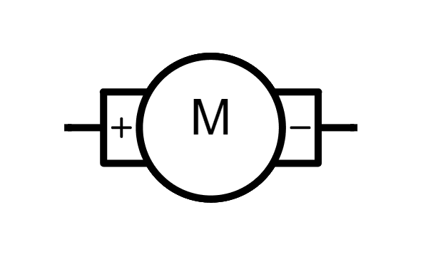
Motors
A motor converts electrical energy into kinetic energy. Its schematic symbol is a circle with the letter “M”, and positive and negative terminals on the left and right:
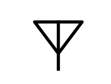
Antennas
An antenna is a device that receives or transmits radio signals. Here’s the schematic symbol for an antenna:
Wires and Connections in Schematics
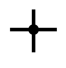
Now that you’re familiar with the common symbols used in schematic diagrams, let’s take a look at how to read wire connections and wire crossings. Wires are represented by lines, and connections are represented by dots.
The images below show the schematic symbols for wires when they are physically connected in a circuit. The dots over the intersections are called nodes:

The absence of a node means that the wires are not connected and just pass by each other, like this:
There is another way to show unconnected wires in a schematic, with a semi-circle over the point where the wires cross, like this:

Now that you’re familiar with the basic schematic symbols and wire connections, you’re now ready to read a simple circuit. Remember to be mindful of the polarities. Below is a simple circuit that consists only of three elements – a battery, an LED, and a resistor:
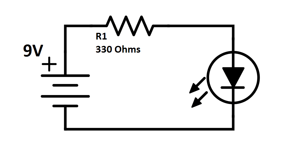
The 9V battery powers the circuit, and the resistor limits the battery’s current so it doesn’t burn out the LED. Remember that the positive side of a diode is the flat edge of the triangle, and the negative side is the straight line.
Understanding how to read schematics will also help you modify a circuit if you want. But it’s also essential for many other uses too, like troubleshooting circuits and designing PCBs.
Hope you found this tutorial helpful! Feel free to leave a comment below if you have a question about anything…


Can you refer me to a site that explains how to translate a schematic into real world electronics? For example, if I see a schematic with a series of lines going up and down and left and right, how do those lines get translated into real wires and connections?
Hi Jon, the lines in a schematic represent the physical wires used to connect a circuit. On a PCB, they represent the copper traces.
Dear sir,
Please help me to understand:
In an Industral Ladder Control Schimatric drawing I am studying, I see number like (3-5)
, (3-54), (68), (4-1), etc above Relay contacts in different rungs. What do these numbers mean?
In the variable resistors you are using photoreister as an example but then two spaces down you have an actual symbol for type photoreister.
Can you provide an example of when one would use the variable resistor symbol when using the photoreister.
Great article! I noticed in some automotive wiring diagrams there are wire segment terminal points with different shapes on them that I believe represent male/female connectors. At first glance they look like your polarized capacitor only with two curved sides, but closer inspection reveals more trapezoidal or even triangular edges (when internal to modules like an instrument cluster). This would be a good addition I think. In text pictures: “—))—” vs. “–>>—” or “–>)–” etc.
What are the methods used to read the diagrams? Usually people read schematic diagrams from left to right or from top to bottom. What about reading detailed diagrams or more complex drawings? Are there other ways? And can the basic types of reading skills be utilized, such as speed reading (skimming and scanning), detailed reading, and deep reading skills? How can these three types of reading be involved in reading schematic diagrams?
I could not see the symbol I saw on my monitor in any of the symbols shown above. It was a round symbol but not a perfect circle. It had a downward arrow alongside the round symbol. There was another thinner downward line (maybe with a small arrow at the end of the line) which was between the round circle and the prominent downward arrow.