In this tutorial, we will set up a wireless web server using an Arduino and an ESP8266-01 WiFi module that will let you post sensor data to a web page that can be viewed from anywhere with an internet connection. Let’s get started!

The Internet
To get you geared up for our project, let us see first how the internet works.
The internet, as we know it, is a global WAN (Wide Area Network) that connects computers around the world. Physically, they are just wires under the ground. A web server is capable of connecting to these “wires” directly. On the other hand, a web client needs to go through a server first to connect to another server or client.
Web Server vs Web Client
A web server is either software, hardware, or a combination of both that contains files needed to process and deliver web pages. A web client is simply any device that can send an HTTP/web request to a web server. HTTP or Hypertext Transfer Protocol is a unique protocol that a web server and web client use to communicate.
To demonstrate, suppose you want to visit www.circuitbasics.com. So you enter the website URL to your web browser. After a few seconds, assuming you are connected to the internet, the Circuit Basics homepage appears.
In this example, your computer is a web client. Your computer sends a web request using a web browser application, i.e., Chrome or Firefox. The web browser sends the request to the web server that hosts Circuit Basics, which then returns the data needed to display the Circuit Basics homepage.
A web server that hosts a website is usually a purpose-built computer that stores a massive amount of data. They have unique IP addresses as well.
Arduino Web Server
But you won’t need any of those unless you are planning to build a large website. An Arduino paired with an ESP8266 module is enough for a simple web server. With an Arduino web server, you can already store a web page and extend control over your sensors and other connected devices. Things like reading sensor values and toggling relay switches can now be done anywhere via a WiFi connection.
Additionally, a web server that can be accessed anywhere via the internet is called a global server. Meanwhile, a web server that can only be visited in your Local Area Network (LAN) is called a local server.
There are many ways to create a global server. In this tutorial, we are going to use a method called port forwarding.
Web Requests
To get data from web servers, web clients use HTTP requests. There are several types of HTTP requests, but you only need to learn two to create an Arduino server. These requests are called HTTP GET and HTTP POST.
HTTP GET is a web request that retrieves data from a web browser. It does not change anything on the server. It just fetches the data from it.
HTTP POST is a web request that transmits data to the server. It adds something new to the server.
A typical example of a GET request is the simple browsing of a website. On the other hand, POST requests are used in typing text into a web page, for instance, a username and password.
The ESP8266-01 Module
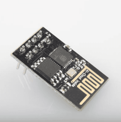
The ESP8266 is a WiFi chip developed by Espressif Systems. It provides a full WiFi networking solution, enabling users to set up a web server or web client with a separate processor or even standalone. It is also Arduino compatible, meaning you can program it using the Arduino IDE.
We are going to use the ESP-01 version module of the chip. It is developed by a third-party manufacturer called AI-Thinker. It has an onboard MCU (Microcontroller Unit), which allows users to control I/O digital pins directly via the Arduino IDE.
Technical Specifications
- 802.11
b/g/n - Integrated
low power 32-bit MCU - Integrated
10-bit ADC - Integrated
TCP/IP protocol stack - Integrated
TR switch, balun, LNA, power amplifier and matching network - Integrated
PLL, regulators, and power management units - Supports
antenna diversity - WiFi 2.4
GHz, support WPA/WPA2 - Support STA/AP/STA+AP
operation modes - Support
Smart Link Function for both Android and iOS devices - Support
Smart Link Function for both Android and iOS devices - SDIO 2.0,
(H) SPI, UART, I2C, I2S, IRDA, PWM, GPIO
ESP8266 Pinout
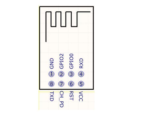
Legend:
- GND – Ground
- GPIO2 – Programmable I/O pin with an internal pull-up resistor
- GPIO0 – Programmable I/O pin with an internal pull-up resistor
- RX – UART Receiving pin
- VCC – 3.3v
- REST – External Reset Pin, Active LOW
- CH_PD – Chip Enable Pin. Active HIGH
- TX – UART Transmitting pin
Setting Up a Local Server
Before we create a global server, we need to understand how a local server works. In order to set up a local server, we need to find a way to send AT commands to the ESP-01. These commands come from the pre-installed AT firmware of the ESP-01. We can either use an FTDI cable to send these directly or we can use a separate processor like the Arduino. In this tutorial, we are going to use an Arduino.
First, you need the following components:
Then, connect the ESP-01 to the Arduino, as shown below:
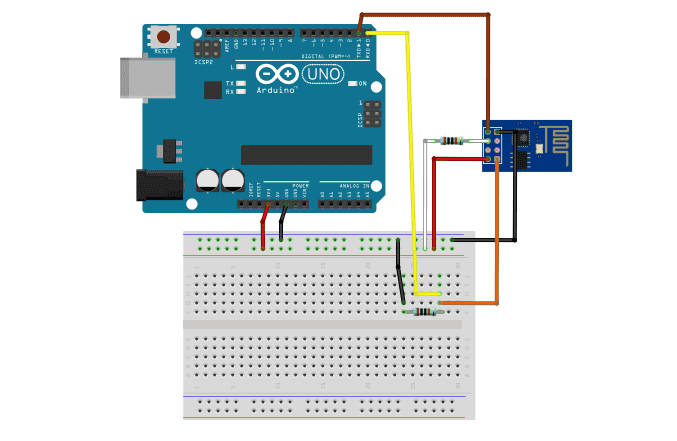
The maximum voltage input of the ESP8266-01 is 3.6V. Always double-check the pins when connecting it to the 3.3V power supply. If you accidentally connect it to the 5-V supply, you risk destroying the module.
Both 1k resistors act as pull up and pull down resistors for the CH_PD and RX pins, respectively.
If you want to learn more about the Arduino, check out our Ultimate Guide to the Arduino video course. You’ll learn basic to advanced Arduino programming and circuit building techniques that will prepare you to build any project.
Using the Arduino IDE
After preparing the hardware, let’s now proceed to the programming.
Open the Arduino IDE. Go to File >> Examples >> Basics >> BareMinimum then upload the sketch. This is to make sure that no program is running on the Arduino board.
Next, open the serial monitor. Make sure to set the baud rate to default, which is usually 115200. Then, type the following AT command: AT.
If you see “OK”, that means the ESP8266-01 is working. If you don’t get a response, briefly connect the RST pin to GND and try again.
ESP8266 AT Commands
The ESP8266 AT Commands allow users to perform operations like testing the connection, setting the mode of operation, connecting to WiFi, determining the IP address, etc.
Setting the Mode
After confirming that your chip is working, set the mode of operation by typing the following AT command: AT+CWMODE=1
The ESP8266-01 has three modes of operation: (1) Station (STA); (2) Access Point (AP); and (3) Both.
In the first mode, you set the WiFi module to act as a Station (STA). The module gains the ability to connect to an available WiFi network.
In the second mode, you set the WiFi module to act as an Access Point (AP). The module acts as a WiFI network where devices like computers can connect to it.
In the third mode, you set the WiFi module to act as both an AP and an STA.
We need to set the module to AP mode if we are going to use it as a web server. To check what mode the ESP8266 is in, type in AT+CWMODE?. The response is going to be number 1, 2, or 3 which corresponds to the mode of operation.
Connecting to WiFi
To connect to a WiFi network, type the following command: AT+CWJAP= “SSID”,“Password”
These are case sensitive, so be sure to type the exact WiFi Network’s name and password. Also, there should be no spaces between the quotation marks and the comma. You are going to get an OK response when successfully connected.
Verify the connection using this AT command: AT+CIFSR
This AT command gives the IP and MAC addresses of the ESP-01. Be sure to take note of both of your IP and MAC addresses because we are going to use that later for port forwarding purposes.
Enabling the Connections
We should also set the ESP-01 to support multiple connections since we need it as a server. To do that, enter this command in the serial monitor: AT+CIPMUX=1
If you need to change it back to a single connection, replace 1 in the AT+CIPMUX command with 0.
Furthermore, start the server using the command: AT+CIPSERVER=1,80 .
The first number indicates the port status. A value of 0 means it is closed while a value of 1 means it is opened. On the other hand, the second number indicates the port number. Port 80 is the default port number for the HTTP protocol, which is also what we use for HTML pages.
At this point, we already established a connection between your home router and the ESP-01. We are now ready to send HTTP requests from your computer to the module.
Sending and Receiving Data
To send a GET request, simply enter your ESP-01’s IP address to your computer’s web browser. This is going to send a response on your serial monitor. The response contains several useful information like the details of the file to be retrieved, the name of the browser used for the request, the operating system, and so on.
Notice that your web browser isn’t displaying anything. That’s because there is still no data to be retrieved.
Let us send the usual “Hello World” to test our connection. Type the following command in your serial monitor: AT+CIPSEND=0,12
The first number indicates what channel the data is going to be transmitted. While the second number indicates the number of characters to be sent. Since we are going to send “Hello World”, we need to set the second number to 12 so that it is sent entirely, including space.
After pressing enter, a > symbol should appear. This means that the server is already waiting for the message. Next, type Hello World on your serial monitor. After a while, the monitor will display SEND OK. Finally, to display the data on your web browser, close the communication channel by typing the following command: AT+CIPCLOSE=0.
As soon as you hit enter, a Hello World message should appear on your web browser.
Setting up a Global Server
Now that we’re done with the local server, we move forward by connecting the ESP-01 to the internet. In this section, we are going to create a global server that displays the date, time, temperature, and humidity on a web page you can access anywhere.
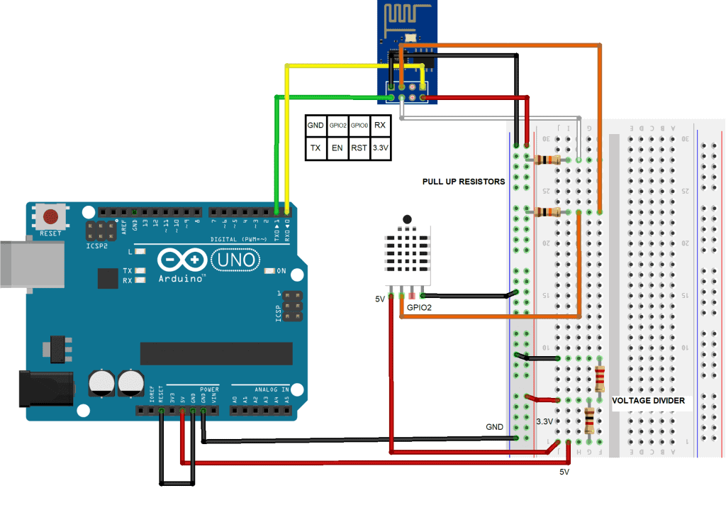
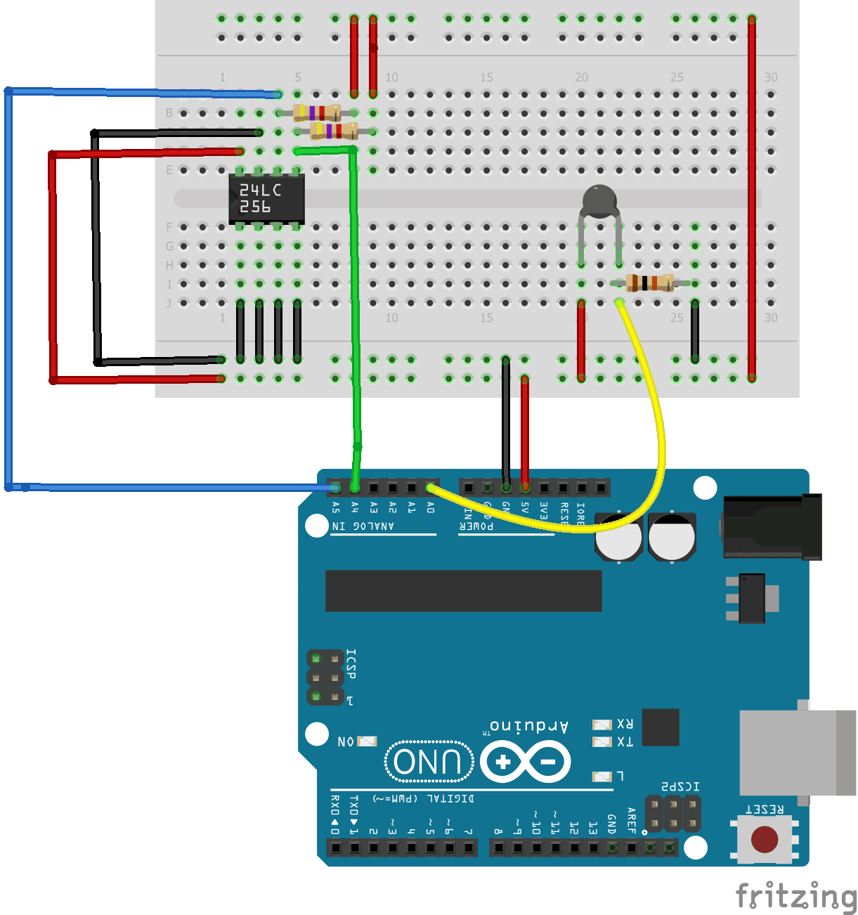
Using the parts listed below, build your Arduino and ESP8266 ESP-01 module as shown in the image below:
- Arduino Uno
- ESP8266 ESP-01 module
- DHT22 temperature and humidity sensor
- Two 10K Ohm resistors
- One 1K Ohm resistor
- One 2.2K Ohm resistor
- Breadboard
- Jumper wires
Previously, we used the serial monitor to send AT commands to the ESP-01. This time we will do the actual programming.
Connecting your Components
Connect the RST (Reset) pin of the Arduino to GND (Ground). Setting the RST to GND disables the chip of the Arduino so that we can use the board as an ESP programmer. Next, we power up the ESP-01. Unlike before, we won’t use the 3.3V supply of the Arduino. We will be needing more current since we are now using a sensor. Fortunately, the 5V pin supplies enough current for both, but we need a voltage divider to change the voltage to 3.3V. Connect a 1kΩ and 2.2kΩ resistor in series, just like in the image above. Connect the end of the series to the ground. Finally, connect the other leg of the 1kΩ resistor to the positive rail of the breadboard. The power rail should already supply 3.3V.
Next, we power up the DHT22. The DHT22 module needs 3.3V – 5V to work. You can connect it to either supply. If you wish to use 5V, connect it to pin before the voltage divider. Then, use a 10k pull-up resistor along the data line that connects the DHT22 and the ESP-01.
Then, to initialize the ESP-01 module, connect the EN/CH-PD (Enable) pin to the 3.3V supply. Use a 10k pull-up resistor.
Finally. connect the ESP-01’s GPIO pin 0 to GND to start program mode.
Programming the ESP8266
To program the ESP8266 chip using the Arduino IDE, you must first install the board then proceed as follows:
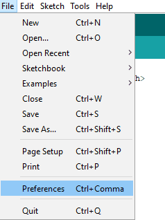
1. In the Arduino IDE, go to File >> Preferences.
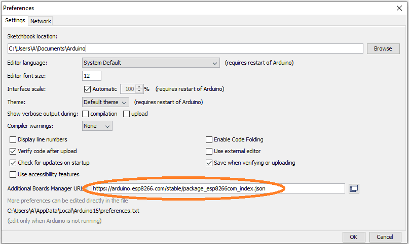
2. In the Additional Boards Manager URL field, enter http://arduino.esp8266.com/stable/package_esp8266com_index.json. Then, press OK.
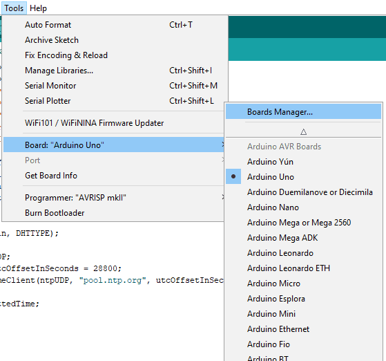
3. Go to Tools >> Board >> Boards Manager.
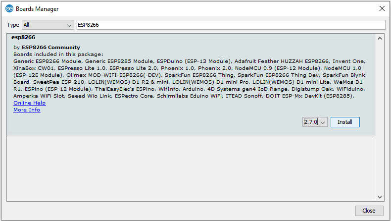
4. In the Boards Manager search bar, enter ESP8266. Then, press install on the “ESP8266 by ESP8266 Community“.
At this point, ESP8266 board definitions are already installed. You can now program the ESP8266 chip just like any other Arduino board.
Programming the ESP8266
First, install all of the required libraries. The ESP8266WiFi.h and the ESP8266WebServer.h are built-in, so they will be available after installing the ESP8266 board in the Boards Manager. These two libraries give access to functions that help you connect to a WiFi network, set up a server, and handle HTTP requests.
The DHT.h library is a library from Adafruit that enables support for DHT temperature and humidity sensors. This library can be downloaded from here.
NTPClient.h and WiFiUdp.h are for NTP server synchronization and UDP protocol handling respectively. The NTPClient library can be downloaded from here. The WiFiUdp.h library is built-in, so there’s no need to install it.
Once the libraries are installed, copy and paste the following sketch into the Arduino IDE, then upload it to the ESP8266:
#include <ESP8266WiFi.h>
#include <ESP8266WebServer.h>
#include <DHT.h>
#include <NTPClient.h>
#include <WiFiUdp.h>

#define DHTPin 2
#define DHTTYPE DHT22
DHT dht(DHTPin, DHTTYPE);

WiFiUDP ntpUDP;
const long utcOffsetInSeconds = 28800;
NTPClient timeClient(ntpUDP, "pool.ntp.org", utcOffsetInSeconds);
unsigned long epochTime = timeClient.getEpochTime();
struct tm *ptm = gmtime ((time_t *)&epochTime);

const char* ssid = "WiFi Name";
const char* password = "WiFi Password";

ESP8266WebServer server(80);

String SendHTML(float TemperatureWeb,float HumidityWeb, String TimeWeb, String DateWeb);
void handle_OnConnect();
void handle_NotFound();

float Temperature;
float Humidity;
String formattedTime;
String Date;
int Day;
int Month;
int Year;

void setup() {
  Serial.begin(115200);
  pinMode(DHTPin, INPUT);

  Serial.println("Connecting to ");
  Serial.println(ssid);

  WiFi.begin(ssid, password);

  while (WiFi.status() != WL_CONNECTED) {
  delay(1000);
  Serial.print(".");
  }
  Serial.println("");
  Serial.println("Connected to WiFi");
  Serial.print("IP: ");  Serial.println(WiFi.localIP());

  server.on("/", handle_OnConnect);
  server.onNotFound(handle_NotFound);
  server.begin();
  dht.begin();
  timeClient.begin();
}
void loop() {

  server.handleClient();

}

void handle_OnConnect() {

  timeClient.update();

  unsigned long epochTime = timeClient.getEpochTime();
  String formattedTime = timeClient.getFormattedTime();

  struct tm *ptm = gmtime ((time_t *)&epochTime);

  int monthDay = ptm->tm_mday;
  int currentMonth = ptm->tm_mon+1;
  int currentYear = ptm->tm_year+1900;

  formattedTime = timeClient.getFormattedTime();
  Date = String(currentYear) + "-" + String(currentMonth) + "-" + String(monthDay);
  Temperature = dht.readTemperature();
  Humidity = dht.readHumidity();
  server.send(200, "text/html", SendHTML(Temperature,Humidity,formattedTime,Date));
}

void handle_NotFound(){
  server.send(404, "text/plain", "Not found");
}

String SendHTML(float TemperatureWeb,float HumidityWeb, String TimeWeb,String DateWeb){
  String ptr = "<!DOCTYPE html> <html>\n";
  ptr +="<head><meta name=\"viewport\" content=\"width=device-width, initial-scale=1.0, user-scalable=no\">\n";
  ptr +="<title>ESP8266 Global Server</title>\n";

  ptr +="</head>\n";
  ptr +="<body>\n";
  ptr +="<div id=\"webpage\">\n";
  ptr +="<h1>ESP8266 Global Server</h1>\n";

  ptr +="<p>Date: ";
  ptr +=(String)DateWeb;
  ptr +="</p>";
  ptr +="<p>Time: ";
  ptr +=(String)TimeWeb;
  ptr +="</p>";
  ptr +="<p>Temperature: ";
  ptr +=(int)TemperatureWeb;
  ptr +="C</p>";
  ptr +="<p>Humidity: ";
  ptr +=(int)HumidityWeb;
  ptr +="%</p>";

  ptr +="</div>\n";
  ptr +="</body>\n";
  ptr +="</html>\n";
  return ptr;
}
Understanding the Code
First we include all of the libraries:
#include <ESP8266WiFi.h>
#include <ESP8266WebServer.h>
#include <DHT.h>
#include <NTPClient.h>
#include <WiFiUdp.h>
Then, to connect to your home WiFi, enter your network credentials here:
const char* ssid = "WiFi Name";
const char* password = "WiFi Password";
Next, we initialize a WifiUDP and NTPClient instance. Setting up an NTPClient object needs a WiFiUDP object, an NTP server, and an offset to specify your time zone. We use pool.ntp.org as the NTP server address. This automatically detects the closest time server from your location. Lastly, for the UTC offset for your timezone, use this formula:
UTC X = X * 60 * 60
I am in GMT+8 so for me,
UTC 8 = 8 * 60 * 60 = 28800
WiFiUDP ntpUDP;
const long utcOffsetInSeconds = 28800;
NTPClient timeClient(ntpUDP, "pool.ntp.org", utcOffsetInSeconds);
The epoch time function returns the number of seconds that have elapsed since January 1, 1970. We use this function along with a time structure to get the date.
unsigned long epochTime = timeClient.getEpochTime();
struct tm *ptm = gmtime ((time_t *)&epochTime);
Now we open port 80 using ESP8266WebServer server(80);.
Then, for the setup, we initialize the serial monitor at 115200 to create prompts and display information. Moreover, using begin functions, we connect to the WiFi, start a server then initialize the DHT sensor and time server.
void setup() {
  Serial.begin(115200);
  pinMode(DHTPin, INPUT);

  Serial.println("Connecting to ");
  Serial.println(ssid);

  WiFi.begin(ssid, password);

  while (WiFi.status() != WL_CONNECTED) {
  delay(1000);
  Serial.print(".");
  }
  Serial.println("");
  Serial.println("Connected to WiFi");
  Serial.print("IP: ");  Serial.println(WiFi.localIP());

  server.on("/", handle_OnConnect);
  server.onNotFound(handle_NotFound);
  server.begin();
  dht.begin();
  timeClient.begin();
}
Following the setup is the loop. The loop section only contains a single line. This line is a function of the ESPWebserver library. It monitors the presence of a web client and handles HTTP requests, just like POST and GET.
void loop() {
  server.handleClient();
}
If handleClient() detects a request from a Web Client and successfully connects, it directs the sketch to the handle_OnConnect() function. Alternatively, if there is an error with the connection, it goes to handle_NotFound().
void handle_OnConnect(){
}
void handle_NotFound(){
}Inside the handle_OnConnect() function are the commands that fetch the current date, time, temperature, and humidity readings from their respective libraries. Using the time structure we set earlier, we get the current date. Whereas for time, we use getFormattedTime() directly from the NTPClient library. Same goes for temperature and humidity, where we use dht.readTemperature() and dht.readHumidity() directly from the DHT library. Finally, server.send() returns the data to the client.
void handle_OnConnect() {

  timeClient.update();

  epochTime = timeClient.getEpochTime();
  String Time = timeClient.getFormattedTime();

  tm *ptm = gmtime ((time_t *)&epochTime);

  int monthDay = ptm->tm_mday;
  int currentMonth = ptm->tm_mon+1;
  int currentYear = ptm->tm_year+1900;

  Time = timeClient.getFormattedTime();
  Date = String(currentYear) + "-" + String(currentMonth) + "-" + String(monthDay);
  Temperature = dht.readTemperature();
  Humidity = dht.readHumidity();

  server.send(200, "text/html", SendHTML(Temperature,Humidity,Time,Date));
}
Last but not least, we use SendHTML() to create a web page according to the data we have collected.
String SendHTML(float TemperatureWeb,float HumidityWeb, String TimeWeb,String DateWeb){
  String ptr = "<!DOCTYPE html> <html>\n";
  ptr +="<head><meta name=\"viewport\" content=\"width=device-width, initial-scale=1.0, user-scalable=no\">\n";
  ptr +="<title>ESP8266 Global Server</title>\n";

  ptr +="</head>\n";
  ptr +="<body>\n";
  ptr +="<div id=\"webpage\">\n";
  ptr +="<h1>ESP8266 Global Server</h1>\n";

  ptr +="<p>Date: ";
  ptr +=(String)DateWeb;
  ptr +="</p>";
  ptr +="<p>Time: ";
  ptr +=(String)TimeWeb;
  ptr +="</p>";
  ptr +="<p>Temperature: ";
  ptr +=(int)TemperatureWeb;
  ptr +="C</p>";
  ptr +="<p>Humidity: ";
  ptr +=(int)HumidityWeb;
  ptr +="%</p>";

  ptr +="</div>\n";
  ptr +="</body>\n";
  ptr +="</html>\n";
  return ptr;
}
Demonstration
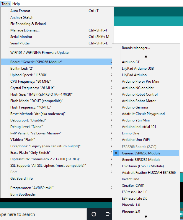
Upload the code to the ESP-01. Choose “Generic ESP8266 Module” as the board. Make sure to select the correct port number as well.
After uploading, open the serial monitor and you should see something like this:
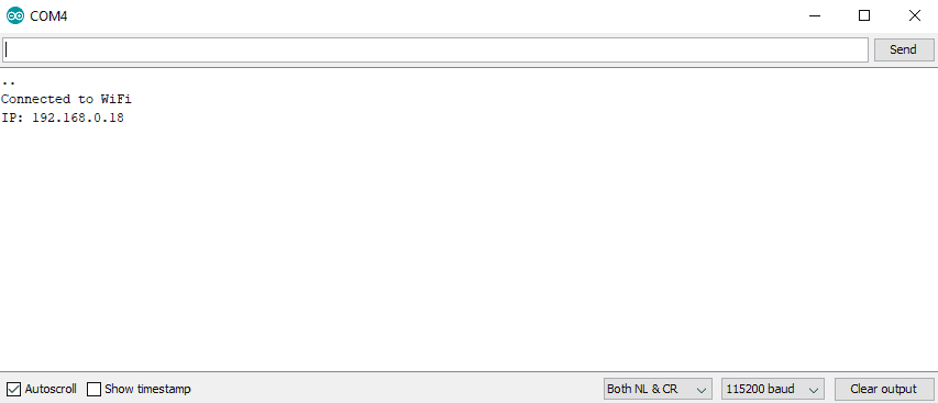
Visit the given IP address using any web browser.
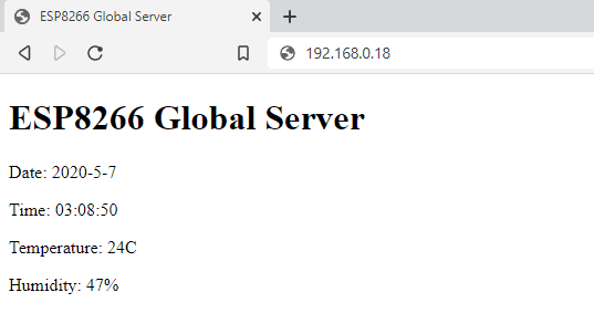
This is still a local server. To make this web page available outside your home network, we need to employ a technique called port forwarding.
Port Forwarding
Port forwarding is a network router feature that directs traffic from a particular port in your WAN to a device inside your LAN. Here’s how to do port forwarding:
1. First, know your WAN IP address. You can do this by simply typing “what is my IP address” into Google.
2. Then, visit your router’s homepage. Enter your router’s gateway IP address in your web browser. Every model varies. For instance, my Hitron Technologies router uses “192.168.0.1”. On the home page, log in.
3. Next, explore the interface. Find out how to change the DHCP settings. Add the ESP-01’s IP Address to static so that it remains fixed. For our example server above, that would be “192.168.0.18”. Also, enter the MAC address you got from the AT+CIFSR command. After applying these, your router then reserves the 192.168.0.18 address to the ESP-01.
4. Next, go to Port Forwarding settings. Create a virtual server using the TCP protocol. Use port 80 then enter the ESP-01’s IP address. Don’t forget to save the changes you’ve made to your router.
5. Last but not least, configure your Firewall Settings to allow port 80 to communicate directly with your devices.
By now, port forwarding is already done. Any incoming HTTP request from your WAN’s port number 80 is now directed to your ESP-01. Visiting your WAN’s IP address outside your network directs you to the web page that displays current day, time, temperature, and humidity.
Be sure to leave a comment if you have any questions!


Hey,
The instructions are amazing but I hit a snag at Programming the ESP8266. The code compiled but it’s not uploading.
this is the error message I get.
Arduino: 1.8.5 (Windows 10), Board: “Generic ESP8266 Module, 80 MHz, Flash, Legacy (new can return nullptr), All SSL ciphers (most compatible), dtr (aka nodemcu), 26 MHz, 40MHz, DOUT (compatible), 1MB (FS:64KB OTA:~470KB), 2, nonos-sdk 2.2.1+100 (190703), v2 Lower Memory, Disabled, None, Only Sketch, 115200”
Archiving built core (caching) in: C:\Users\HP\AppData\Local\Temp\arduino_cache_155979\core\core_esp8266_esp8266_generic_xtal_80,vt_flash,exception_legacy,ssl_all,ResetMethod_nodemcu,CrystalFreq_26,FlashFreq_40,FlashMode_dout,eesz_1M64,led_2,sdk_nonosdk_190703,ip_lm2f,dbg_Disabled,lvl_None____,wipe_none,baud_115200_b6331d768e07ee5a5abdf3b507ed4505.a
Executable segment sizes:
IROM : 262904 – code in flash (default or ICACHE_FLASH_ATTR)
IRAM : 27604 / 32768 – code in IRAM (ICACHE_RAM_ATTR, ISRs…)
DATA : 1264 ) – initialized variables (global, static) in RAM/HEAP
RODATA : 1160 ) / 81920 – constants (global, static) in RAM/HEAP
BSS : 25400 ) – zeroed variables (global, static) in RAM/HEAP
Sketch uses 292932 bytes (30%) of program storage space. Maximum is 958448 bytes.
Global variables use 27824 bytes (33%) of dynamic memory, leaving 54096 bytes for local variables. Maximum is 81920 bytes.
esptool.py v2.8
Serial port COM10
Connecting…….._____….._____….._____….._____….._____….._____….._____
Traceback (most recent call last):
File “C:\Users\HP\AppData\Local\Arduino15\packages\esp8266\hardware\esp8266\2.6.2/tools/upload.py”, line 65, in
esptool.main(cmdline)
File “C:/Users/HP/AppData/Local/Arduino15/packages/esp8266/hardware/esp8266/2.6.2/tools/esptool\esptool.py”, line 2890, in main
esp.connect(args.before)
File “C:/Users/HP/AppData/Local/Arduino15/packages/esp8266/hardware/esp8266/2.6.2/tools/esptool\esptool.py”, line 483, in connect
raise FatalError(‘Failed to connect to %s: %s’ % (self.CHIP_NAME, last_error))
esptool.FatalError: Failed to connect to ESP8266: Invalid head of packet (0xF0)
esptool.FatalError: Failed to connect to ESP8266: Invalid head of packet (0xF0)
Invalid library found in C:\Users\HP\Arduino\libraries\AFMotor: C:\Users\HP\Arduino\libraries\AFMotor
Invalid library found in C:\Users\HP\Documents\Arduino\libraries\Magnetic_Suspension: C:\Users\HP\Documents\Arduino\libraries\Magnetic_Suspension
Invalid library found in C:\Users\HP\Documents\Arduino\libraries\Sequential: C:\Users\HP\Documents\Arduino\libraries\Sequential
Invalid library found in C:\Users\HP\Documents\Arduino\libraries\Vu_meter: C:\Users\HP\Documents\Arduino\libraries\Vu_meter
This report would have more information with
“Show verbose output during compilation”
option enabled in File -> Preferences.
Can you please help me out. I’ve tried several other places but your article looks the best.
Try to downgrade your ESP8266 board library in the Boards Manager to version 2.5.0. Don’t forget to briefly connect then disconnect the ESP-01 reset pin to GND before uploading the program.
I managed to compile and upload the code by connect GPIO0 to GND, but nothing showed up on the serial monitor.
A great tutorial for a newbie like me. Thanks for providing information to make the IP address of the ESP static. After setting a Global server, we can view the live data of the sensors from anywhere, but we can’t store the data for future analytics. Right?
Hi! I´m trying to upload the bare minimum code to the Arduino, everything is connected as shown in the first image, however, I´m receiving the error message shown below, how can I fix this? Thanks!
Sketch uses 444 bytes (1%) of program storage space. Maximum is 32256 bytes.
Global variables use 9 bytes (0%) of dynamic memory, leaving 2039 bytes for local variables. Maximum is 2048 bytes.
avrdude: stk500_getsync() attempt 1 of 10: not in sync: resp=0x30
avrdude: stk500_getsync() attempt 2 of 10: not in sync: resp=0x20
avrdude: stk500_getsync() attempt 3 of 10: not in sync: resp=0x30
avrdude: stk500_getsync() attempt 4 of 10: not in sync: resp=0x20
avrdude: stk500_getsync() attempt 5 of 10: not in sync: resp=0x30
avrdude: stk500_getsync() attempt 6 of 10: not in sync: resp=0x20
avrdude: stk500_getsync() attempt 7 of 10: not in sync: resp=0x30
avrdude: stk500_getsync() attempt 8 of 10: not in sync: resp=0x20
avrdude: stk500_getsync() attempt 9 of 10: not in sync: resp=0x30
avrdude: stk500_getsync() attempt 10 of 10: not in sync: resp=0x20
An error occurred while uploading the sketch
I managed to fix that, however, no I am having issues with the reading of temperture (I’m getting 0ºC or 2147483647ºC) and humidity (I get 0% or 6553%)
Well done. Thank you.
How would you modify the code so date, time and data were updated automatically on a set period?
Many thanks for this article which allowed me to make progress with my Arduino Nano 33 Sense BLE. Your method of step by step explanation is a model for others to follow.
Arduino: 1.8.15 (Windows 10), Board: “Arduino Uno”
testforfinal:1:10: fatal error: ESP8266WiFi.h: No such file or directory
#include
^~~~~~~~~~~~~~~
compilation terminated.
exit status 1
ESP8266WiFi.h: No such file or directory
Invalid library found in C:\Users\user\Documents\Arduino\libraries\SimulatorProgram: no headers files (.h) found in C:\Users\user\Documents\Arduino\libraries\SimulatorProgram
This report would have more information with
“Show verbose output during compilation”
option enabled in File -> Preferences.