9-axis sensors combine a magnetometer, accelerometer, and a gyroscope into a single sensor. The small size and low weight of these sensors make them perfect for building aircraft, drone, and robot navigation systems.

In this article, we will see how 9-axis sensors work, how to connect them to an Arduino, and finally how to program them to get readings from each axis. The sensor we’re going to use is the MPU-9250 9-axis sensor.
Watch the video for this tutorial here:
Overview of the MPU-9250 9-Axis Sensor
The MPU-9250 has three different sensors – a magnetometer, an accelerometer, and a gyroscope. Each sensor outputs data from the X, Y, and Z axes. That makes 9 axes in total, so the MPU-9250 is a 9-axis, or 9 degree of freedom sensor. Degrees of freedom are the total number of axes that can be measured by a sensor.
Here’s a pin diagram of the MPU-9250:
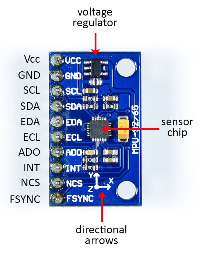
The MPU-9250 has ten pins:
- VCC: Power input. If the MPU-9250 PCB has a voltage regulator on it, it can be connected to either 3.3 or 5 volts. If no voltage regulator is present, the maximum voltage is 3.3 volts.
- GND: Connects to ground on the Arduino.
- SCL: For I2C communication. Doubles as the SCLK pin for SPI communication.
- SDA: For I2C communication. Doubles as the SDI pin for SPI communication.
- EDA: I2C master serial data pin. The MPU-9250 can be setup as an I2C master device to receive and output data from another sensor. This pin would connect to the SDA pin of the other sensor.
- ECL: I2C master serial clock pin. Would connect to the SCL pin of the other sensor.
- ADO: Used to change the I2C address of the sensor. When it’s low the I2C address is 0x68. When it’s high the address is 0x69. Doubles as the SDO pin for SPI communication.
- INT: Hardware interrupt pin. Can trigger a hardware interrupt from any of the sensor’s 9 axes.
- NCS: The CS pin for SPI communication.
- FSYNC: Frame synchronization digital input pin. Used to pass the hardware interrupt from an external sensor to the Arduino.
On top of the MPU-9250 PCB there should be some directional arrows that indicate the direction of the accelerometer and gyroscope axes in relation to the PCB board.
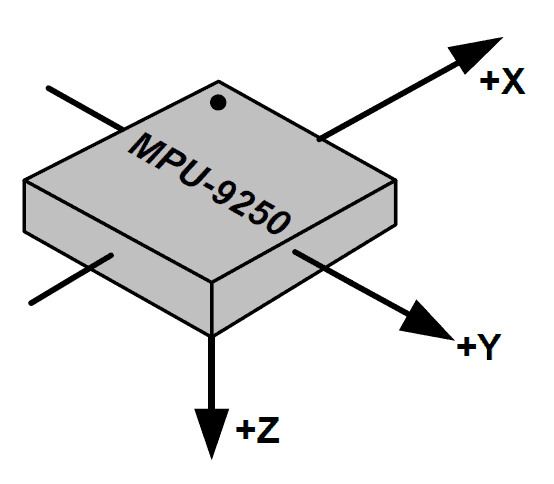
The magnetometer’s axes are aligned differently. It might be hard to see but there is a small dot on the upper left hand corner of the sensor chip. The magnetometer axes are oriented like this in relation to that dot:
How to Connect the MPU-9250 to the Arduino
The MPU-9250 can communicate with the Arduino over SPI or I2C communication. In this project we will use I2C.
Here are the parts you’ll need to build the project:
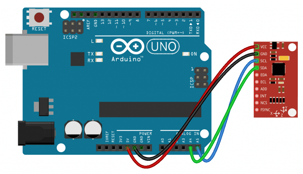
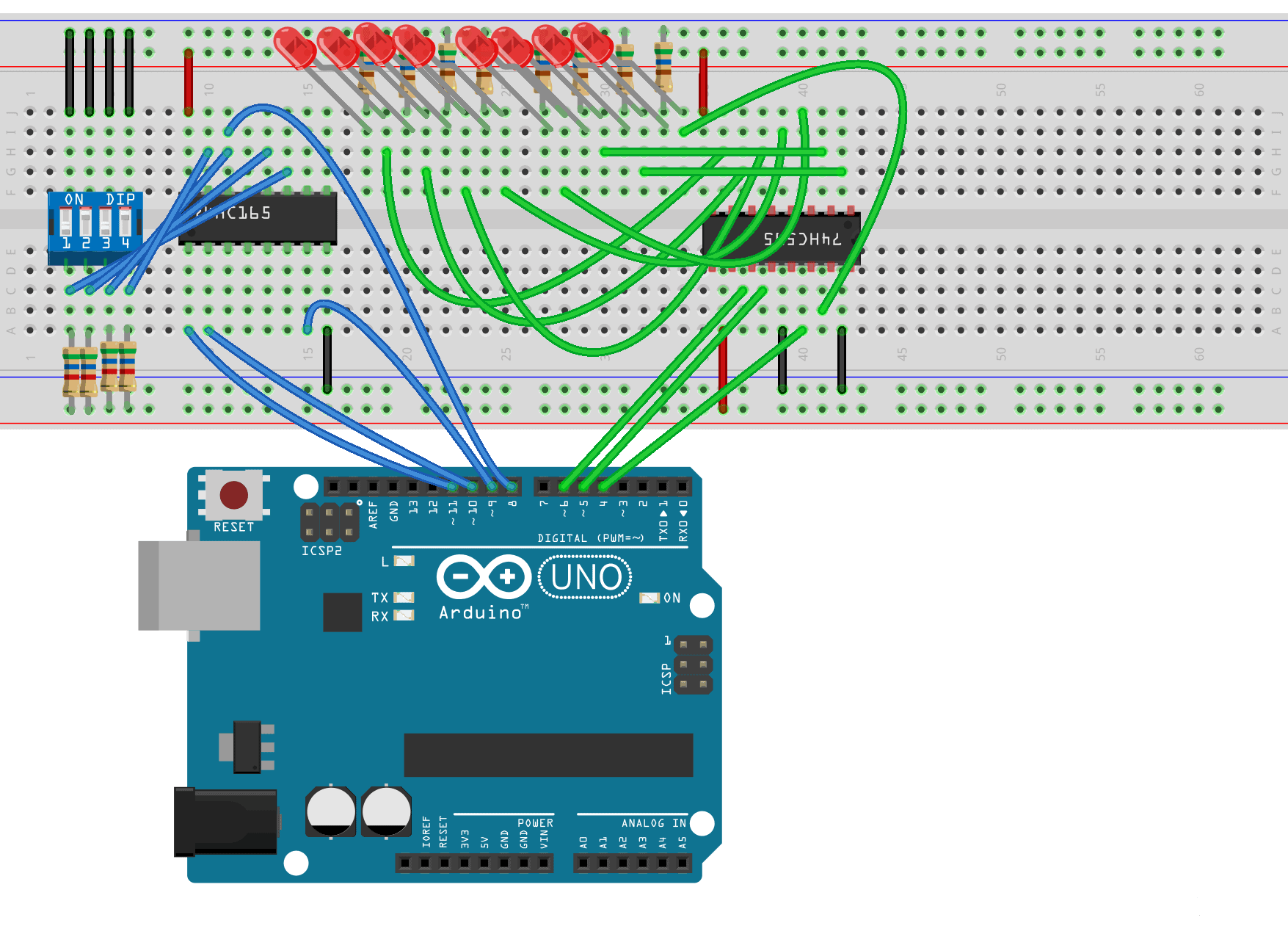
Follow the wiring diagram below to connect the MPU-9250 to the Arduino:
How to Program the MPU-9250 on the Arduino
The sketch below will print out the reading from each axis to the serial monitor. We will use a library called the MPU9250 library to program the sensor. You can download it from this link. Once the library is installed, upload this code to the Arduino:
#include "MPU9250.h"

MPU9250 sensor(Wire, 0x68);

void setup() {
  Serial.begin(9600);
  sensor.begin();
}

void loop() {

  sensor.readSensor();

  Serial.print("Accelerometer X: ");
  Serial.println(sensor.getAccelX_mss(), 2);
  Serial.print("Accelerometer Y: ");
  Serial.println(sensor.getAccelY_mss(), 2);
  Serial.print("Accelerometer Z: ");
  Serial.println(sensor.getAccelZ_mss(), 2);

  Serial.print("Gyroscope X: ");
  Serial.println(sensor.getGyroX_rads(), 2);
  Serial.print("Gyroscope Y: ");
  Serial.println(sensor.getGyroY_rads(), 2);
  Serial.print("Gyroscope Z: ");
  Serial.println(sensor.getGyroZ_rads(), 2);

  Serial.print("Magnetometer X: ");
  Serial.println(sensor.getMagX_uT(), 2);
  Serial.print("Magnetometer Y: ");
  Serial.println(sensor.getMagY_uT(), 2);
  Serial.print("Magnetometer Z: ");
  Serial.println(sensor.getMagZ_uT(), 2);

  Serial.print("Temperature: ");
  Serial.println(sensor.getTemperature_C(), 2);

  Serial.println("------------------------------------");

  delay(500);
}
Explanation of the Code
The first thing we do is include the MPU9250 library with #include "MPU9250.h". On the next line, we declare a sensor object from the MPU9250 class. We need to pass the communication protocol we’re using and the I2C address of the sensor to the sensor object. For I2C communication, use Wire as the first parameter. The second parameter is the I2C address. We left the ADO pin unconnected (low) so the I2C address is 0x68. If it was connected it to 5 volts, the I2C address would be 0x69.
To connect the sensor with SPI communication, use SPI for the first parameter and the Arduino pin connected the sensor’s CS pin as the second parameter.
In the setup() section, we initialize the serial monitor and initialize the sensor object with sensor.begin().
In the loop() section, we first get a reading from the sensor with the readSensor() function, which is called through the sensor object.
Now we can print the sensor readings to the serial monitor. The reading from each axis can be retrieved by calling the following functions through the sensor object:
- Accelerometer X axis:
getAccelX_mss() - Accelerometer Y axis:
getAccelY_mss() - Accelerometer Z axis:
getAccelZ_mss() - Gyroscope X axis:
getGyroX_rads() - Gyroscope Y axis:
getGyroY_rads() - Gyroscope Z axis:
getGyroZ_rads() - Magnetometer X axis:
getMagX_uT() - Magnetometer Y axis:
getMagY_uT() - Magnetometer Z axis:
getMagZ_uT()
In the program above, the reading from each sensor’s axis is printed on a separate line. The Serial.print() function let’s you use a second parameter to specify how many digits you want to display after the decimal. We want to display two digits after the decimal, so we have a 2 as the second parameter of each Serial.print() function.
The MPU-9250 has a built in digital temperature sensor. The temperature reading can be printed by using sensor.getTemperature_C() as the first parameter of the the Serial.print() function.
Since there are so many sensor readings, we will print a line of dashes to separate the sensor readings obtained in each cycle of the loop. At the end of the loop() section is a delay of 500 milliseconds to slow down the output and make it easier to read.
Once the MPU-9250 is connected to your Arduino and the sketch above is uploaded, open up the serial monitor. You should see readings like this getting printed out:
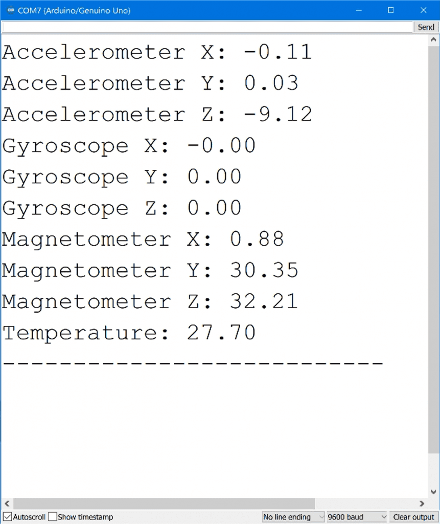
The three accelerometer axes are printed first, in meters per second squared. Notice that the X and Y axes are close to zero, but the Z axis is -9.12. The sensor was lying flat on a table with the Z axis facing up and down when these measurements were taken, so this is caused by the acceleration from gravity.
The gyroscope’s X, Y, and Z values are printed next, in radians per second. The sensor wasn’t rotating along any of it’s axes when these measurements were taken so they are all zero.
Next are the magnetometer readings for each axis in microteslas, followed by the temperature reading in degrees Celsius.
If you have any questions or trouble setting up the MPU-9250 9-axis sensor, feel free to leave a comment below and we will try to help you out!

Scott, Thanks again for this outstanding article and great explanation of both the sensor, and how the code works in Arduino. I have a few questions and hope you will be able to respond. What I am trying to do is derive the ‘position’ of the Arduino+9 axis module in 3D space from the output data of the 9-axis module for a drone application.
Q1: I read somewhere that all these 9-axis sensors have to be calibrated prior to get accurate output. How do you calibrate all 9 axes when power is applied to Arduino? If I can calibrate all axes, can I combine calibration code with this code?
Q2: I also read that the MPU output has to be temperature compensated for accurate output, so how can I use these temperature readings with the MPU output?
Q3: If the combined output of the MPU needs to be used for deriving the ‘position’, would it not need to be read on the exact time stamp? To do this, will I need and RTC module? If so, how do I wire RTC module (and perhaps other sensors such as a barometer for accurate elevation with the MPU unit to Arduino?
Q4: How do I combine all the outputs from MPU to derive “position” as X, Y, Z, values in linear measure such as cm or meter which can be used further in another application?
I would sincerely appreciate if you can help and thank you in advance. Please keep your excellent articles coming. They are the best! I am learning a lot!
The offsets on the X & Y axis imply that the calibration will need to be at least a ‘line fit’ calibration. That is, you’ll need to do fit a line through some ‘known’ sample measurements and derive coefficients for the line equation Y = mX +b where X is the raw value, Y is the corrected value. m is the linear error of the axis and b is the offset.
I don’t have this sensor, I did develop a calibration process for the DS18B20 before I retired. It would be interesting to see the returned values for X,Y and Z when the sensor is rotated so each axis is subjected to acceleration of gravity.
The acceleration of gravity is 9.8 M/sec^2 – so it appears the sensor is using those units.
There will be an accumulation of error if you use the reported acceleration to compute current velocity and then position.
Have you considered using this device to control the attitude of the drone and a GPS chip to determine the position?