GPS sensors can provide real time position data in your Arduino projects. By detecting latitude, longitude, altitude, velocity, and heading, they’re an indispensable tool for autonomous vehicles and other devices where the global position needs to be known. In this article, we will set up a GPS sensor on the Arduino and learn how to work with the data it provides.

Watch the video for this tutorial here:
Overview of a GPS Sensor
The GPS we are going to use is the Adafruit Ultimate GPS Breakout. It’s one of the more reliable GPS units you can get:
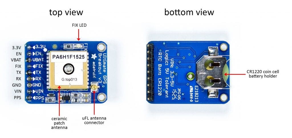
The Adafruit Ultimate GPS Breakout uses the MTK3339 GPS chip from MediaTek. The GPS chip is located underneath the tan ceramic patch antenna. The GPS has uFL connection that is used to connect an external antenna. The FIX LED blinks to let you know if there’s a satellite fix. On the bottom side is a coin cell battery holder so the GPS can keep satellite fixes after the main power is turned off. The GPS can be powered with either 3.3 volts or 5 volts.
The Ultimate GPS Sensor Breakout has nine pins:
- VIN – Used to power the GPS. It connects to either 3.3 volts or 5 volts.
- 3.3V – Provides a 3.3 volt power supply that can power other devices.
- EN – Enable pin. It’s high by default but if pulled low the GPS will turn off.
- VBATT – Battery pin. It’s connected to the positive terminal of the coin cell battery. This is where you can input 3.3 volts from a coin cell battery on another device.
- FIX – Connected to the fix LED. When the LED is on the pin will be high and when the LED is off the pin will be low.
- TX – Used to transfer data from the GPS to the Arduino.
- RX – Used to send commands from the Arduino to the GPS.
- GND – Connects to the Arduino’s ground pin.
- PPS – Pulse per second. It outputs a signal to synchronize other microcontrollers to the GPS. Not needed with the Arduino.
How GPS Works
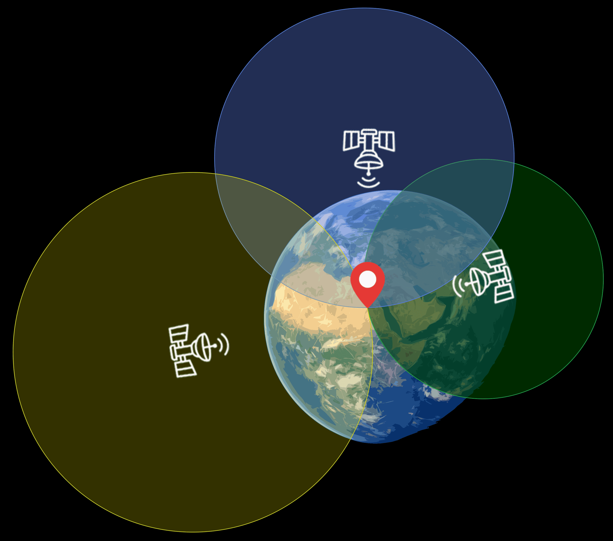
GPS uses triangulation to detect your position anywhere on Earth. Global positioning satellites orbiting the Earth transmit a radio signal with information about its location and current time. The GPS sensor receives that signal and calculates the distance to the satellite, based on how long it took the signal to reach the sensor. That places the sensor on a radius equal to the distance from the satellite to the sensor. By taking distance measurements to multiple satellites, the sensor can determine its precise location relative to the satellites.
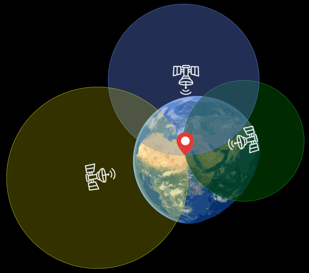
When the GPS sensor is able to detect and receive a signal from a satellite, it’s called a “fix”. The GPS sensor needs a fix with at least three satellites to get a location reading. Having a fix with more satellites will give you a more accurate location.
How to Connect and Program the GPS to Get Raw Data
In order to access the latitude, longitude, and other data from the GPS, we need to take a look at the raw data output by the sensor. In this project we will connect the GPS to the Arduino and output the raw GPS data to the serial monitor.
Here are the parts you will need:
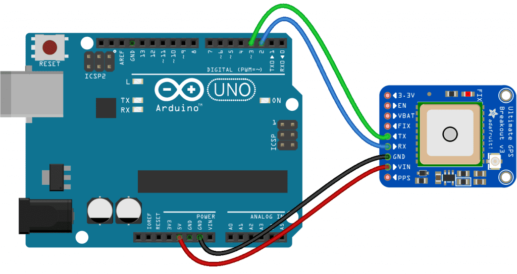
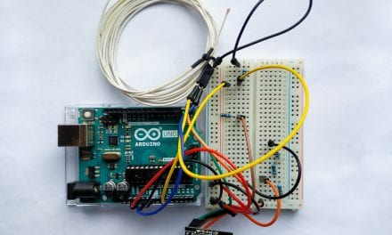
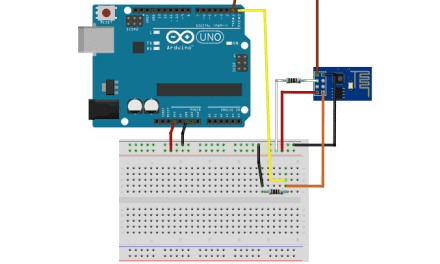
The GPS uses TTL serial communication to send data to the Arduino, so we can view the sensor readings on the serial monitor without any code. To get the raw GPS readings, connect your GPS to the Arduino like this:
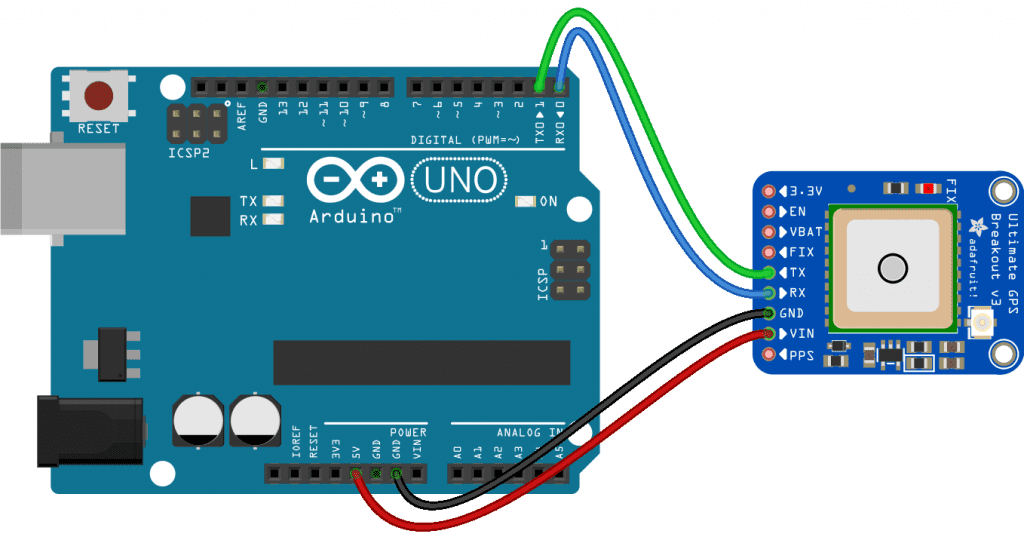
Now open the serial monitor in the Arduino IDE and you should see the raw GPS readings being printed out:
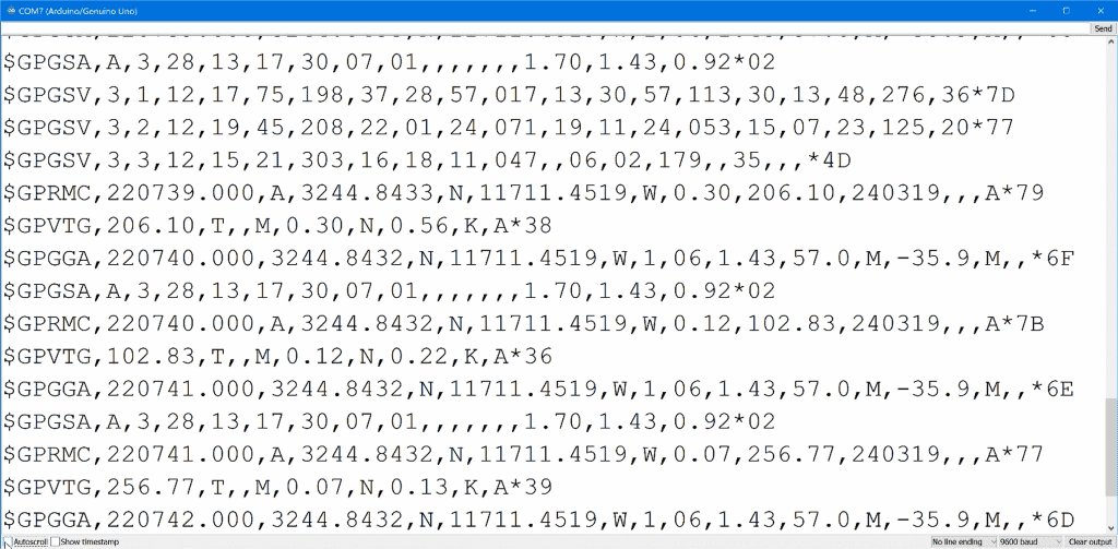
The raw GPS sensor data is provided in NMEA sentences.
What are NMEA Sentences?
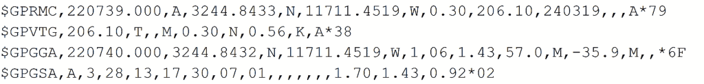
There are four different NMEA sentences in each sensor read – GPRMC, GPVTG, GPGGA, and GPGSA:
The GPRMC Sentence
The GPRMC sentence is the one we will be using the most. GPRMC stands for Global Positioning Recommended Minimum Coordinates. It has most of the location information we’re interested in. Each piece of information is separated by a comma:
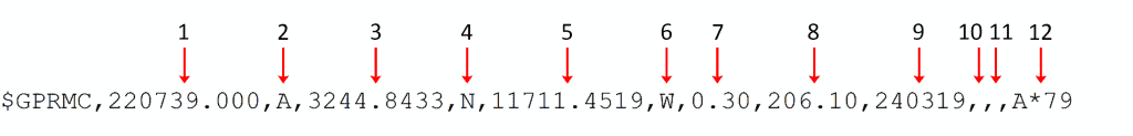
Here are the details about each part of the GPRMC sentence:
- Current time in Greenwich mean time.
- Status code. If the NMEA sentence is valid and the GPS had a satellite fix when it got the data, this will be “A” for active. If it’s a “V” the data in the NMEA sentence is void and should not be used.
- Latitude position in the format DDMM.MMMM. The first two digits are the degrees, the second two digits are the minutes, and the four digits after the decimal are the fractional component of the minutes value.
- Cardinal direction of latitude position. Will be “N” north of the equator and “S” south of the equator.
- Longitude position in the format DDDMM.MMMM. The first three digits are the degrees, the second two digits are the minutes, and the four digits after the decimal are the fractional part of the minutes value.
- Cardinal direction of longitude position. Will be “E” east of the prime meridian or “W” west of the prime meridian.
- Ground speed in knots.
- Course made good reading. This is the direction the GPS is travelling, independent of the direction it’s pointing in degrees from true north.
- Date of satellite fix. The date of the satellite fix in the format DDMMYY.
- Magnetic variation (AKA magnetic declination) for your current location. It can be used to convert the course made good value into a heading in degrees. The value is in degrees, along with a value for the cardinal direction.
- Direction of the magnetic variation. Will be either “E” for east or “W” for west.
- Checksum. Used to verify that the sentence was transferred to the Arduino without errors.
The GPVTG Sentence
The next sentence is the GPVTG sentence:

The GPVTG sentence contains the track made good and ground speed values.
The GPGGA Sentence
The sentence after that is the GPGGA sentence:

The GPGGA sentence contains data about the fix quality and number of satellites with a fix.
The GPGSA Sentence
The last sentence is the GPGSA sentence:

The GPGSA sentence contains more information about the fix quality.
To convert the NMEA sentences into a format we can work with, we need to parse them.
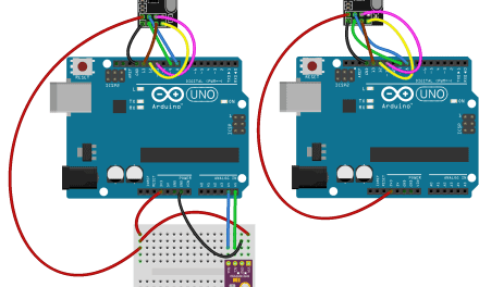
How to Parse the NMEA Sentences
Parsing simply means to read some text and convert it into something easier to read. To parse the NMEA sentences, we have to connect the GPS to the Arduino like this.
Programming the GPS Sensor for Parsed NMEA Sentences
We will use the Adafruit GPS library to program the sensor. You can download it here.
Once the library is installed, upload this sketch the the Arduino:
#include <Adafruit_GPS.h>
#include <SoftwareSerial.h>

SoftwareSerial mySerial(3, 2);
Adafruit_GPS GPS(&mySerial);

char c;

void setup() {
  Serial.begin(9600);
  GPS.begin(9600);

  GPS.sendCommand(PMTK_SET_NMEA_OUTPUT_RMCGGA);

  GPS.sendCommand(PMTK_SET_NMEA_UPDATE_1HZ);
  delay(1000);
}

void loop() {

  clearGPS();

  while (!GPS.newNMEAreceived()) {
    c = GPS.read();
  }

  GPS.parse(GPS.lastNMEA());

  Serial.print("Time: ");
  Serial.print(GPS.hour, DEC);
  Serial.print(':');
  Serial.print(GPS.minute, DEC);
  Serial.print(':');
  Serial.print(GPS.seconds, DEC);
  Serial.print('.');
  Serial.println(GPS.milliseconds);

  Serial.print("Date: ");
  Serial.print(GPS.day, DEC);
  Serial.print('/');
  Serial.print(GPS.month, DEC);
  Serial.print("/20");
  Serial.println(GPS.year, DEC);

  Serial.print("Fix: ");
  Serial.print(GPS.fix);
  Serial.print(" quality: ");
  Serial.println(GPS.fixquality);
  Serial.print("Satellites: ");
  Serial.println(GPS.satellites);

  if (GPS.fix) {
    Serial.print("Location: ");
    Serial.print(GPS.latitude, 4);
    Serial.print(GPS.lat);
    Serial.print(", ");
    Serial.print(GPS.longitude, 4);
    Serial.println(GPS.lon);
    Serial.print("Google Maps location: ");
    Serial.print(GPS.latitudeDegrees, 4);
    Serial.print(", ");
    Serial.println(GPS.longitudeDegrees, 4);

    Serial.print("Speed (knots): ");
    Serial.println(GPS.speed);
    Serial.print("Heading: ");
    Serial.println(GPS.angle);
    Serial.print("Altitude: ");
    Serial.println(GPS.altitude);
  }
  Serial.println("-------------------------------------");
}

void clearGPS() {
  while (!GPS.newNMEAreceived()) {
    c = GPS.read();
  }
  GPS.parse(GPS.lastNMEA());

  while (!GPS.newNMEAreceived()) {
    c = GPS.read();
  }
  GPS.parse(GPS.lastNMEA());
}
Explanation of the Code
First we include the Adafruit GPS and Software Serial libraries. The Adafruit GPS library has all of the functions needed to parse the NMEA sentences. The Software Serial library creates a new serial port so we can connect the Tx and Rx GPS pins to any Arduino digital pin.
Next we create an object called mySerial from the SoftwareSerial class. We pass the object two parameters. The first parameter is the Arduino pin that is connected to the Rx pin on the GPS. The second parameter is the Arduino pin connected to the Tx pin on the GPS.
Then we create another object called GPS to use the functions in the Adafruit GPS library. We need to pass the mySerial object to the GPS object.
Now we declare a variable called c with the char data type. Each NMEA sentence is a string of characters, so the c variable will hold the individual characters in the string while it’s being read.
In the setup() section we initialize the serial monitor, then initialize the GPS with the begin() function. The begin() function is called through the GPS object. We pass the begin() function the default baud rate of the GPS, which is 9600.
Next we tell the sensor which NMEA sentences we want to receive. The Adafruit GPS library has a function called sendCommand(). If we use PMTK_SET_NMEA_OUTPUT_RMCGGA as a parameter, the GPS will only send the GPRMC and GPGGA sentences:
GPS.sendCommand(PMTK_SET_NMEA_OUTPUT_RMCGGA);
If you only need the GPRMC sentence, change the parameter to PMTK_SET_NMEA_OUTPUT_RMCONLY:
GPS.sendCommand(PMTK_SET_NMEA_OUTPUT_RMCONLY);
If you want all of the sentences, change the parameter to PMTK_SET_NMEA_OUTPUT_ALLDATA:
GPS.sendCommand(PMTK_SET_NMEA_OUTPUT_ALLDATA);
Then we use the sendCommand() function again to set the update rate of the GPS. The update rate specifies how fast the GPS sends location data to the Arduino. Using PMTK_SET_NMEA_UPDATE_1HZ as the parameter sets the update rate to one Hertz:
GPS.sendCommand(PMTK_SET_NMEA_UPDATE_1HZ);
You can change the update rate to 5 Hertz by using PMTK_SET_NMEA_UPDATE_5HZ:
GPS.sendCommand(PMTK_SET_NMEA_UPDATE_5HZ);
Or you can set it to 10 Hertz by using PMTK_SET_NMEA_UPDATE_10HZ:
GPS.sendCommand(PMTK_SET_NMEA_UPDATE_10HZ);
It takes some time for the sensor to start up and perform these commands, so we have a delay of 1,000 ms to let the GPS initialize before we start reading NMEA sentences from it.
Before we read a set of NMEA sentences, we need to clear out the serial buffer to make sure there isn’t any old data in it. In the loop() section, the clearGPS() function clears out the serial buffer for the next set of NMEA sentences. The clearGPS() function is defined at the bottom of the sketch. To clear the serial buffer we need take a reading from the GPS, parse the sentence, and then do nothing with it. This is done twice, once for each NMEA sentence. Once that’s done, we return to the loop() section.
The NMEA sentences will be output from the GPS at a rate of 1 Hz, or once per second. Therefore we need to tell the Arduino to wait until a valid NMEA sentence is ready to be read. We do that with while (!GPS.newNMEAreceived()). This while loop makes the Arduino loop and wait until a NMEA sentence is ready to be read.
The newNMEAreceived() function returns a true value when a new set of NMEA sentences have been received, and a false value when no NMEA sentences have been received. If no NMEA sentence is available to read, the NOT operator makes the condition true. So the program enters the while statement, where the read() function reads the characters coming in through the serial bus. The characters are stored in the c variable. If an NMEA sentence is ready, the newNMEAreceived() function will return a true value. The NOT operator will make the condition false so the program skips the while loop and continues on with the rest of the sketch.
Once a valid NMEA sentence has been received from the GPS, we can parse it with the parse() function. The lastNMEA() function returns the last NMEA sentence received. So if we use lastNMEA() as the parameter in the parse() function, the sketch will take the last NMEA sentence received and parse it.
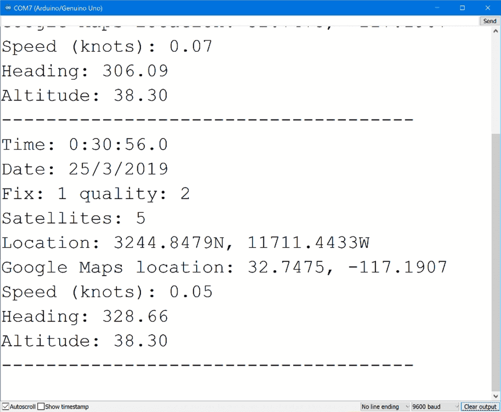
Now that all of the NMEA sentences have been parsed, we can print the data to the serial monitor. The following variables can be used to print data to the serial monitor or be used as inputs into other functions. Note that each variable needs to be accessed through the GPS object as shown below:
GPS.hour– Hour of read (GMT)GPS.minute– Minute of read (GMT)GPS.seconds– Second of read (GMT)GPS.milliseconds– Millisecond of read (GMT)GPS.day– Day of readGPS.month– Month of readGPS.year– Year of readGPS.fix– Returns a 1 if the GPS has a satellite fix and a 0 if it doesn’tGPS.fixquality– Returns a value indicating how strong the satellite fix isGPS.satellites– Returns how many satellites the GPS has a fix onGPS.latitude– Returns the numeric raw latitude value formatted the same way as the NMEA sentenceGPS.lat– Returns the cardinal direction of the latitude (N or S)GPS.longitude– Returns the numeric raw longitude value formatted the same way as the NMEA sentenceGPS.lon– Returns the cardinal direction of the longitude (E or W)GPS.latitudeDegrees– Returns the latitude in degreesGPS.longitudeDegrees– Returns the longitude in degreesGPS.speed– Returns the speed in knotsGPS.angle– Returns the heading in degreesGPS.altitude– Returns the altitude in meters
How to Use the GPS on the Arduino
Once you’ve connected the GPS sensor to your Arduino and uploaded the sketch, wait until the FIX LED starts blinking to indicate satellite fixes. It will blink once per second when there’s no satellite fix , and once every 15 seconds when there is a fix.
For best results, take the GPS outside where there is a clear view of the sky. Depending on where you are, it can take about a minute or longer to get a fix. Once the GPS gets a fix on a few satellites, you’ll see data like this being printed out on the serial monitor:
Be sure to leave a comment below if you have any questions or have trouble setting this up!


maybe do this on an RPi (all versions) using AWK and not a mystery-library to get and display the information?