LED matrixes are ideal for displaying text since they can be seen easily from far distances. This is why signs in train stations, airports, and roadways are commonly made from different configurations of LED matrixes.

The most common type of LED matrix used with the Arduino is the 8×8 LED matrix. Individual 8×8 matrixes can be combined to make larger displays. In this article, we will see how to print text to both individual and combined LED matrix displays. As an example project, we will also see how to scroll the readings from a temperature sensor across the display.
Watch the video for this tutorial here:
What is an LED Matrix?
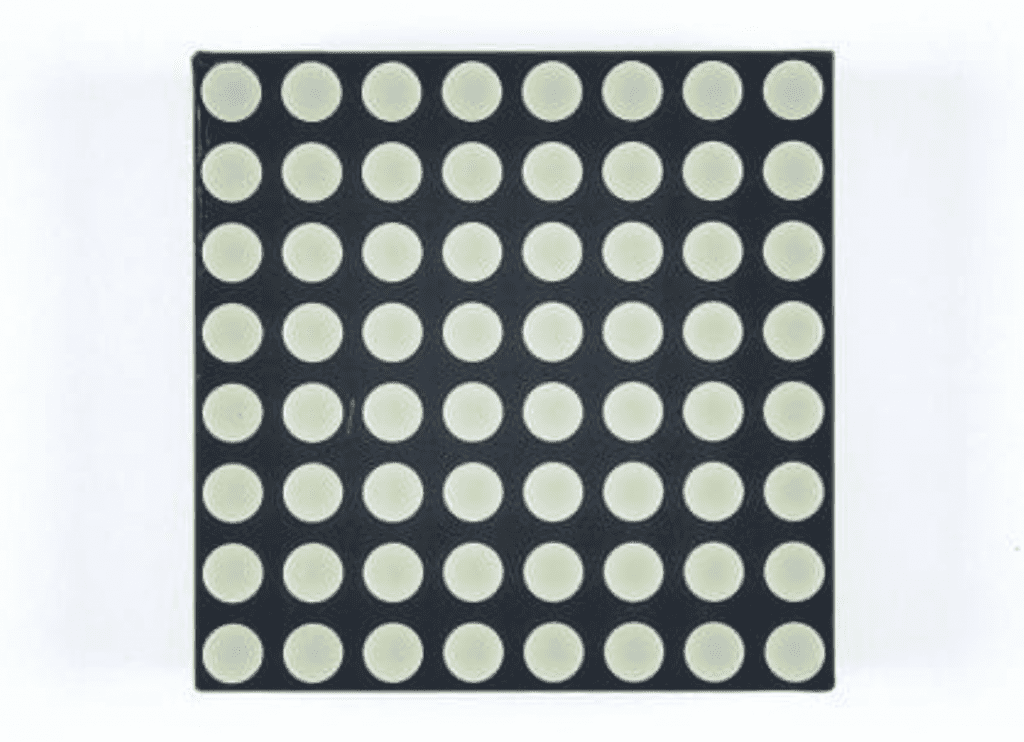
LED matrixes consist of an array of LEDs arranged in a grid. This display has a total of 64 LEDs in 8 rows and 8 columns:
Most LED matrixes have red LEDs, but they are also available with green or blue LEDs. Some even let you control the color of each LED individually.
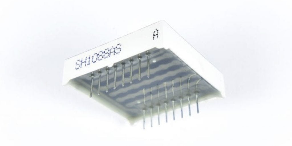
The 1088AS LED Matrix
We will use the 1088AS 8×8 LED matrix in this article. The 1088AS a stand alone matrix, so we’ll have to connect it to an LED driver.
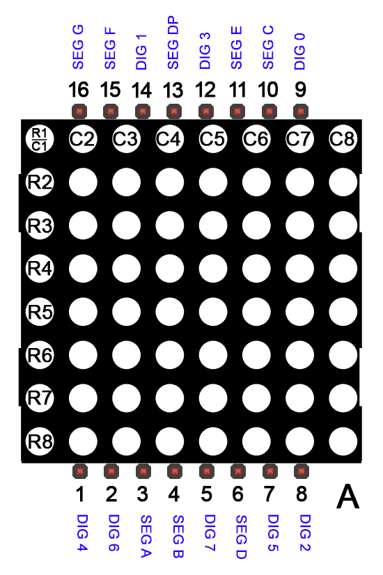
The 1088AS matrix has 16 pins:
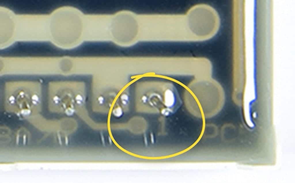
Figuring out the pin numbers on stand alone displays can be a little tricky. The 1088AS has a number one underneath the resin on the bottom side of the display to indicate pin 1:
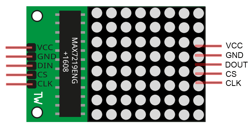
There are also breakout boards with the MAX7219 already connected:
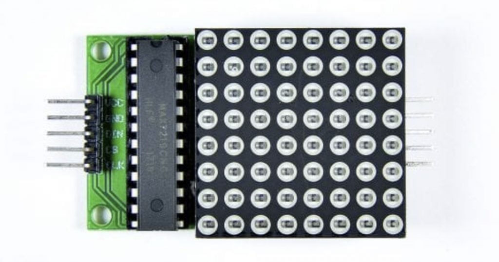
These are much easier to set up. They only have five pins:
- VCC connects to 5V
- GND connects to ground
- DIN is the data input pin
- CS is the chip select pin
- CLK is the clock signal pin
It’s a standard SPI interface. On the back side of the board there is another set of pins that can be used to connect additional displays.
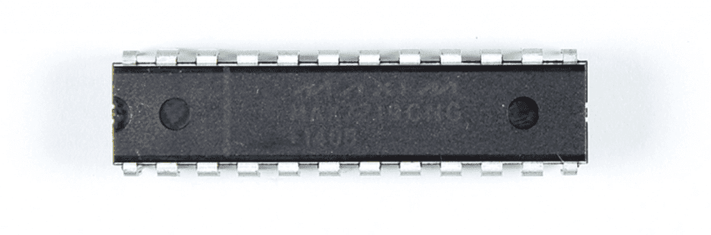
The MAX7219 LED Driver
The LED driver we will use is a chip called the MAX7219:
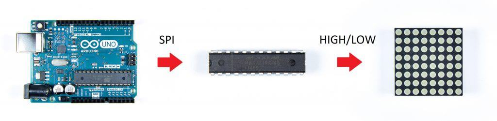
The Arduino will connect to the MAX7219 and send commands to it with the SPI communication protocol. Based on commands from the Arduino, the MAX7219 will output high or low signals to turn each LED on and off:
How LED Matrixes Work
LED matrixes have multiple rows and columns of LEDs. Each LED can be controlled separately. In the 1088AS LED matrix there are 8 rows and 8 columns of LEDs:
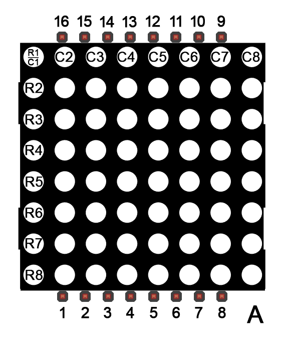
There are also 16 separate pins. In my 1088AS display, there’s an “A” printed on the side of the display next to pin 8. If you’re not sure which pins are which, check the back of your display. There should be at least one pin number under the resin backing.
Here’s the schematic for a 1088AS LED matrix:
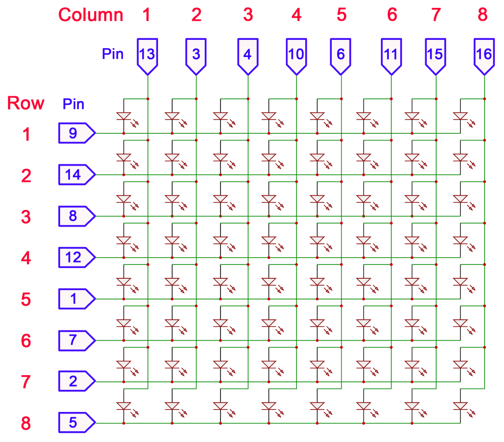
The numbers in blue are the LED matrix pins. The numbers in red are the row and column numbers of the LED that each pin controls. The LEDs can be controlled individually by setting a particular pin high and another pin low. For example, to turn on the LED in row 3, column 7, you would set pin 8 low and set pin 15 high. The pin numbers might be different if you’re using a different display.
Row Cathode vs Row Anode
The 1088AS LED matrix is a row cathode, column anode display. Row cathode means that the cathode of each LED is connected to a row trace. Column anode means that the anode of each LED is connected to a column trace.
Some displays are row anode, column cathode. In these displays the polarity of the LEDs are reversed to what is shown in the schematic above.
Connecting a MAX7219 to an LED Matrix
If you’re connecting a stand alone LED matrix to the Arduino, it’s easiest to start by connecting the LED matrix to the MAX7219 first. Here’s a pin diagram of the MAX7219:
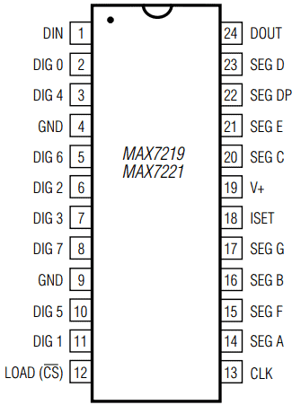
The MAX7219 has 24 pins:
- GND (2) – Connects to ground on the Arduino
- V+ – Connects to 5V on the Arduino
- DIN – The data input pin
- DOUT – The data output pin
- CLK – The clock pin for SPI communication
- LOAD (CS) – Chip select pin for SPI communication
- ISET – Sets the maximum current supplied to the LED matrix
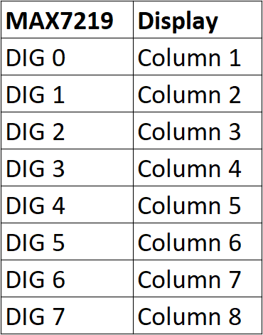
- DIG 0-7 – The digit pins that connect to the LED columns on the LED matrix. Each pin controls an individual LED column:
- SEG A-G, DP – The segment pins that connect to the LED rows on the LED matrix. Each segment pin controls an individual LED row:
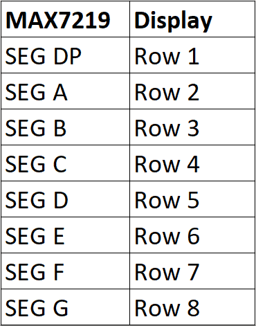
So with the 1088AS LED matrix, the connections to the MAX7219 will look like this:
If you’re using a different display, check the display’s datasheet to determine which pin is connected to each row and column, then connect the display to the MAX7219 accordingly.
Connecting a 1088AS LED Matrix and MAX7219 to the Arduino
Here are the parts you will need:
If you are using the 1088AS display, follow this wiring diagram to connect it to the MAX7219 and the Arduino:
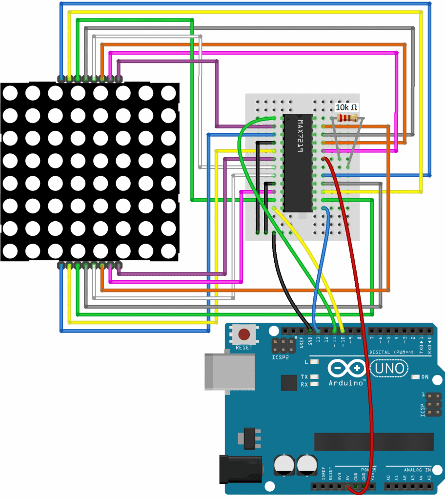
The resistor in the diagram above is the RSET resistor. It connects the ISET pin to Vcc to set the amount of current supplied to the LEDs. The exact value of RSET depends on the type of display you’re using, and there is plenty of discussion on the web about the right value to use. But for most cases, a 10K resistor works fine, so that’s what we’re using here.
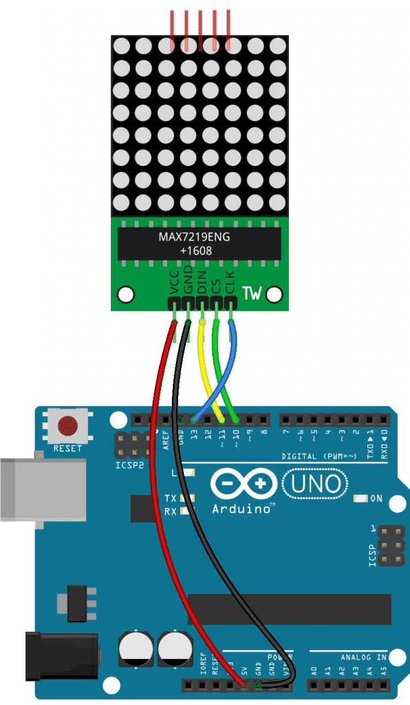
How to Connect an LED Matrix Breakout Board to the Arduino
Connecting an LED matrix to the Arduino is a lot simpler with a breakout board that has the MAX7219 already connected to the display.
These are the parts you will need:
Follow this wiring diagram to connect a breakout board display to the Arduino:
How to Program an LED Matrix on the Arduino
Luckily, the programming is the same for LED matrixes wired to the MAX7219 directly and for LED matrix breakout boards.
We will use the MAX72xxPanel library from Adafruit to program the display. The MAX72xxPanel library uses another library called the Adafruit GFX library. So first you need to download and install the Adafruit GFX library from this link:
https://github.com/adafruit/Adafruit-GFX-Library
Then download and install the Adafruit MAX72xxPanel library from this link:
https://github.com/markruys/arduino-Max72xxPanel
Once the two libraries are installed, upload the code below the Arduino. The sketch will print a single custom character to the display:
#include <SPI.h>
#include <Adafruit_GFX.h>
#include <Max72xxPanel.h>

int pinCS = 10;
//Din connects to pin 11
//CLK connects to pin 13

int numberOfHorizontalDisplays = 1;
int numberOfVerticalDisplays = 1;

Max72xxPanel matrix = Max72xxPanel(pinCS, numberOfHorizontalDisplays, numberOfVerticalDisplays);

const unsigned char PROGMEM smiley[] = {
  B00000000,
  B01000010,
  B00000000,
  B00011000,
  B10000001,
  B01000010,
  B00111100,
  B00000000
};

void setup() {
  matrix.setIntensity(10);
}

void loop() {
  matrix.drawBitmap(0, 0, smiley, 8, 8, HIGH);
  matrix.write();
}
Explanation of the Code
The first thing we need to do is include the libraries. The MAX7219 communicates with the Arduino via SPI, so we need to include the SPI library. We also need to include the Adafruit GFX and MAX72xxPanel library. Then we declare an int variable called pinCS that defines which Arduino pin the CS pin of the MAX7219 is connected to. In this case it’s connected to pin 10. The Din and CLK pins are already defined in the GFX library, so we don’t need to define them here. The Din pin needs to connect to Arduino pin 11, and the CLK pin needs to connect to Arduino pin 13. Then we declare two more variables, numberOfHorizontalDisplays, and numberOfVerticalDisplays. This is where you set the number of horizontal and vertical displays if you have more than one LED matrix set up. We’re just using one display here, so I’ve set both of these to one.
Next we create an object for the display called matrix, which is a member of the MAX72xxPanel class. We pass it the pinCS, numberOfHorizontalDisplays, and numberOfVerticalDisplays variables.
Then we define the character we want to display with an array of bytes. The array consists of eight bytes, with each byte on a separate line. Each byte corresponds to one row of LEDs on the LED matrix. Each byte has eight bits. Each bit corresponds to the column LED in that row. A 1 means the LED will be turned on, and a 0 means the LED will be turned off. The byte array will print a smiley face to the display. An array like this is also known as a bitmap. There are websites online that will generate the bitmap code, like this one.
The bit array is declared as a const unsigned char. One requirement of using bitmaps with the Adafruit GFX library is that they need to be declared with a PROGMEM variable modifier. The PROGMEM variable modifier tells the Arduino to store the array in flash memory instead of in SRAM where variables are usually stored.
In the setup() section, we use the setIntensity() function called through the matrix object to set the brightness of the display. Here it’s set to 10, but it will take arguments from 1 to 15, with 15 being the brightest.
In the loop() section, we print the smiley face we defined in the bitmap with the drawBitmap() function. This function takes six parameters. The first parameter is the X coordinate of the display where the character will be printed from. The second parameter is the Y coordinate. So 0, 0 will print the bitmap starting at the upper left hand corner of the display. The third parameter is the name of the bit array we want to print, smiley. The fourth parameter sets the bitmap width, and the fifth parameter sets the bitmap height. The 1088AS is an 8×8 display, so they are set to 8, 8. If we were using a 16×16 LED matrix, these parameters would be set to 16, 16. The sixth parameter sets the color of the pixels. The 1088AS display only has one color (red) so instead of using a color value here, it’s just set to HIGH.
Next we use the write() function, also called through the matrix object. This function sends the bitmap to the display. It needs to be placed after the drawBitmap() function.
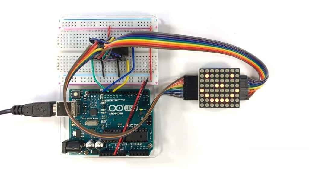
After the circuit is connected and the code is uploaded to the Arduino, you should see something like this on your LED matrix:
How to Connect Multiple LED Matrixes to the Arduino
The easiest way to make a display with multiple LED matrixes is to use breakout boards. Otherwise, you’ll have to connect a separate MAX7219 to each LED matrix, and that would take a lot of wiring. With breakout board LED matrixes, you can connect as many as you want and control all of them with only three data wires.
LED matrix breakout boards have two sets of pins. One set of pins is for the input and the other set of pins is for the output:
The set of pins on the left with the DIN pin is the input side, and the set on the right with the DOUT pin is the output side. The Arduino will connect to the input side and additional displays will connect to the output side.
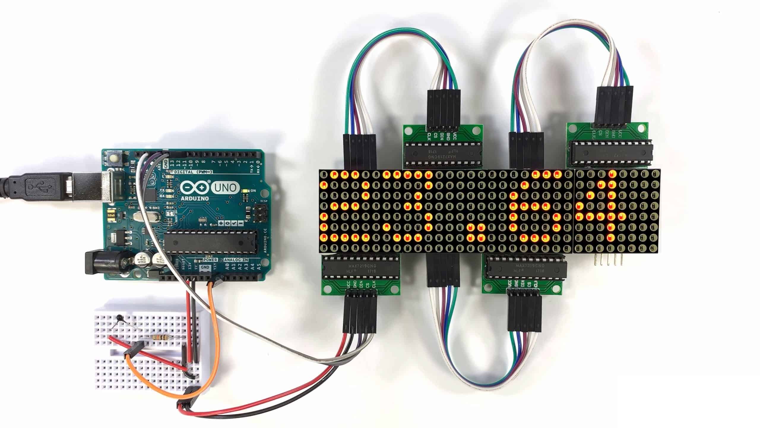
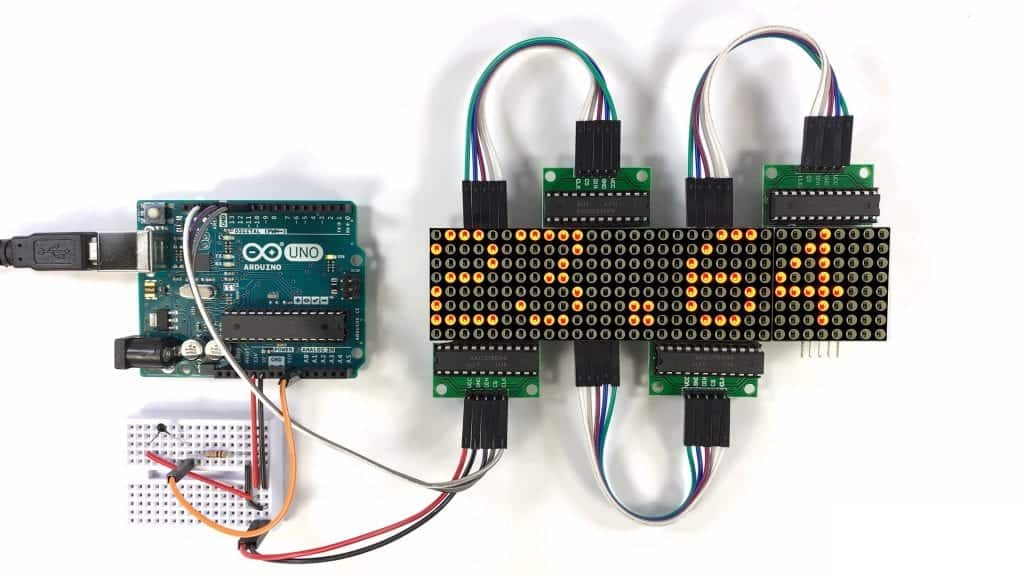
Let’s build a display with four LED matrixes and scroll some text across all four of them.
These are the parts you will need:
Connect the matrixes to the Arduino according to this wiring diagram:
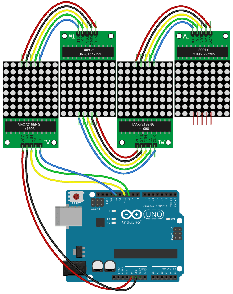
Note that DOUT on the first display connects to DIN on the second display, and so on for the remaining displays.
How to Program Multiple LED Matrixes on the Arduino
Once the LED matrixes are connected, upload the code below to the Arduino. The sketch will scroll a string of text across the four displays.
#include <SPI.h>
#include <Adafruit_GFX.h>
#include <Max72xxPanel.h>

int pinCS = 10;
//Din connects to pin 11
//CLK connects to pin 13

int numberOfHorizontalDisplays = 4;
int numberOfVerticalDisplays = 1;

Max72xxPanel matrix = Max72xxPanel(pinCS, numberOfHorizontalDisplays, numberOfVerticalDisplays);

String tape = "Hello World!";
int wait = 50;
int spacer = 1;
int width = 5 + spacer;

void setup() {
  matrix.setIntensity(7);
  matrix.setRotation(1, 2);
  matrix.setRotation(3, 2);
}

void loop() {

  for (int i = 0 ; i < width * tape.length() + matrix.width() - 1 - spacer; i++ ) {

    matrix.fillScreen(LOW);

    int letter = i / width;
    int x = (matrix.width() - 1) - i % width;
    int y = (matrix.height() - 8) / 2;

    while ( x + width - spacer >= 0 && letter >= 0 ) {
      if ( letter < tape.length() ) {
        matrix.drawChar(x, y, tape[letter], HIGH, LOW, 1);
      }

      letter--;
      x -= width;
    }

    matrix.write();

    delay(wait);
  }
}
The code in this sketch is a bit too complicated to explain here in depth, so I’m just going to point out the important parts.
Since we have four horizontal displays, we need to set numberOfHorizontalDisplays equal to 4 when we declare it. The number of vertical displays is still one, so numberOfVerticalDisplays is still set equal to 1.
The text you want to scroll goes in the line that says String tape = "Hello World!". This sketch prints “Hello World!” to the displays, but if you want to print something else, just change the text inside the quotation marks.
We also declare an int variable called wait. The wait variable defines the speed that the text will scroll across the display in milliseconds. As it is now, the text will shift by one LED column every 50 milliseconds. If you increase the number, the text will scroll slower. If you decrease it, the text will scroll faster.
In the wiring diagram above, the second and fourth displays are connected upside down to make it easier to wire them together. So we need to change the rotation of those displays so they don’t display upside down text. We do that with the setRotation() function. This function takes two parameters. The first parameter is the number of the LED matrix, which is zero indexed. So the second display is display 1, and the fourth display is display 3. The second parameter is the display rotation. Starting from 0°, which is no rotation, the screen can be rotated clockwise in 90° increments by increasing the value by one. So a 1 will rotate the display clockwise 90° and a 2 will rotate it 180° clockwise, which is what we want.
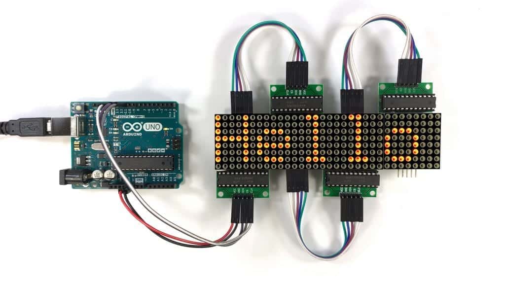
After the circuit is connected and the code is uploaded to the Arduino, you should see the text “Hello World!” scrolling across the four displays:
How to Display Sensor Data on an LED Matrix
Scrolling plain text is nice, but let’s scroll some sensor data across the display too. As an example, we can scroll the temperature reading from a thermistor.
Here are the parts you will need:
- Arduino Uno
- Jumper wires
- Breadboard
- Four 8×8 LED matrix breakout boards
- 10K Ohm thermistor
- 10K Ohm resistor
Connect the LED matrixes and the thermistor to the Arduino following this diagram:
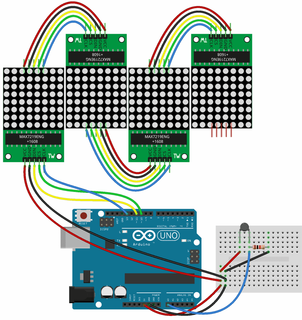
The circuit uses a 10K Ohm thermistor and a 10K Ohm resistor in a voltage divider. This is just an example, so don’t worry too much about the details of how thermistors work. The main thing here is to show you how to print sensor data that’s stored in a variable. But if you want to learn more about thermistors, check out our article on How to Setup a Thermistor on an Arduino.
Code for Displaying Sensor Data on an LED Matrix
Once the circuit above is connected, upload this code to the Arduino:
#include <SPI.h>
#include <Adafruit_GFX.h>
#include <Max72xxPanel.h>

int pinCS = 10;
//Din connects to pin 11
//CLK connects to pin 13

int numberOfHorizontalDisplays = 4;
int numberOfVerticalDisplays = 1;

int thermistorPin = A0;
float R1 = 10000;
float R2, logR2, logR2Cube, tK, tC, tF;
float A = 9.76086e-04, B = 2.38890e-04, C = 2.27e-07;

Max72xxPanel matrix = Max72xxPanel(pinCS, numberOfHorizontalDisplays, numberOfVerticalDisplays);

int wait = 50;
int spacer = 1;
int width = 5 + spacer;

void setup() {
  matrix.setIntensity(7);
  matrix.setRotation(1, 2);
  matrix.setRotation(3, 2);
}

void loop() {

  int Vout = analogRead(thermistorPin);

  R2 = R1 * (1023.0 / Vout - 1.0);
  logR2 = log(R2);
  logR2Cube = pow(logR2, 3);
  tK = (1.0 / (A + B * logR2 + C * logR2Cube));
  tC = tK - 273.15;
  //tF = (tC * 9.0) / 5.0 + 32.0;

  String tape = "Temp: " + String(tC) + " C";

  for (int i = 0 ; i < width * tape.length() + matrix.width() - 1 - spacer; i++ ) {
    matrix.fillScreen(LOW);

    int letter = i / width;
    int x = (matrix.width() - 1) - i % width;
    int y = (matrix.height() - 8) / 2;

    while ( x + width - spacer >= 0 && letter >= 0 ) {
      if ( letter < tape.length() ) {
        matrix.drawChar(x, y, tape[letter], HIGH, LOW, 1);
      }

      letter--;
      x -= width;
    }

    matrix.write();
    delay(wait);
  }
}
Explanation of the Code
Most of the code in this sketch is the same as the sketch we used to scroll text across the four displays, with a few differences. First we declare the float variables for the thermistor calculations.
In the loop() section, the first five lines of code take an analog read of the thermistorPin, perform a calculation to convert the ADC value to Celsius, and store the temperature in a variable called tC.
Next we create the tape object from the String class, and set it equal to a regular text string that says Temp:. Strings can be added, or “concatenated” to each other with a + sign. So all we need to do is concatenate the tC variable to the text string. But since tC is an float variable, we need to convert it to a string before it can be printed. We can do that with String() and the name of the variable inside the parentheses. We’ll also want the units of temperature, so let’s concatenate a C for Celsius after the tC variable is printed.
The rest of the sketch scrolls the tape object across the displays. After everything is connected and the code is running, the temperature detected by the thermistor should be scrolling across the four displays:
Feel free to leave a comment below if you have questions about anything!

I have been lead to believe that the plural of matrix is ‘matrices’.
It can also be matrixes.
Hello I get the letters vertically as I can rotate it horizontally, I put your max72xx library.
My 8×32 matrix module connected to each other, can you help me?
Be proud of what you’ve done here Scott.
I’m a software engineer doing a project for myself with the Max7219.
Software ?, no problem, hardware … another kettle of fish!
I have scoured the internet for incite and clarity;
This article is the most complete and most helpful by far.
Big thankyou.
Thanks Owen!