Push buttons can be used to control LEDs, relays, motors, and pretty much anything else you can think of.

In this article, we will learn how to connect and program a push button on the Arduino. We will also learn about floating pins, pull up and pull down resistors, the digitalRead() function, and the Arduino’s internal pull up resistor. After reading this article, you’ll be able to add push buttons to any project.
Watch the video for this tutorial here:
Introduction to Push Buttons
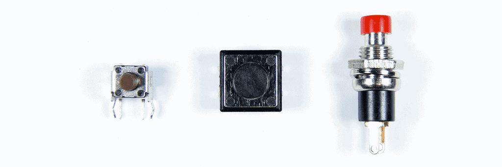
Push buttons are available in a variety of different formats:
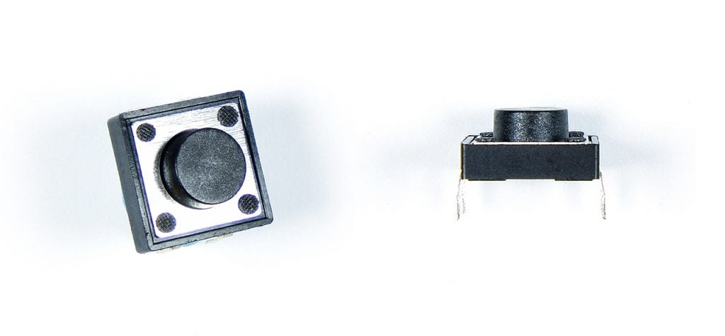
The push button we will use in this article is also known as a tactile switch or momentary push button:
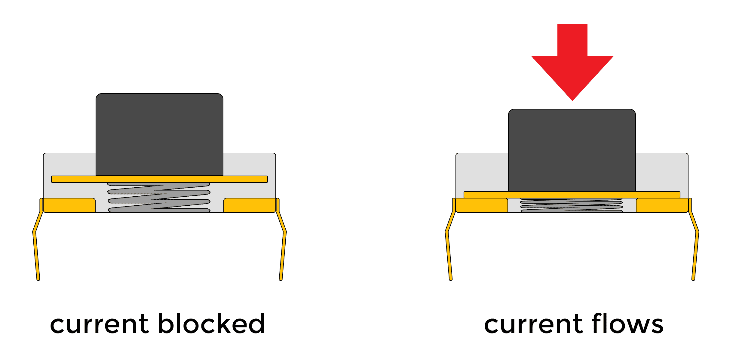
The pins on each side of the button have electrical contacts inside the button housing. The button itself has an electrically conductive piece of metal attached to it. When the button is pressed, the circuit is closed between the pins on each side and current is allowed to flow between them:

Example Project
To demonstrate how to control devices with a push button, let’s build a circuit that turns on an LED when the button is pressed. The LED is just an example, you can use this circuit to control any device powered by a 5 volt signal.
These are the parts needed to build the project:
- Arduino Uno
- Jumper wires
- Breadboard
- SN74HC14N Schmitt trigger
- Tactile push button
- 10K Ohm resistor
- 1 uF capacitor
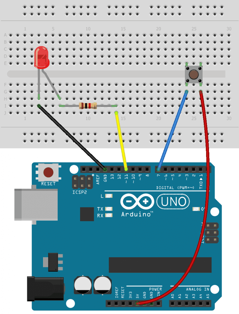
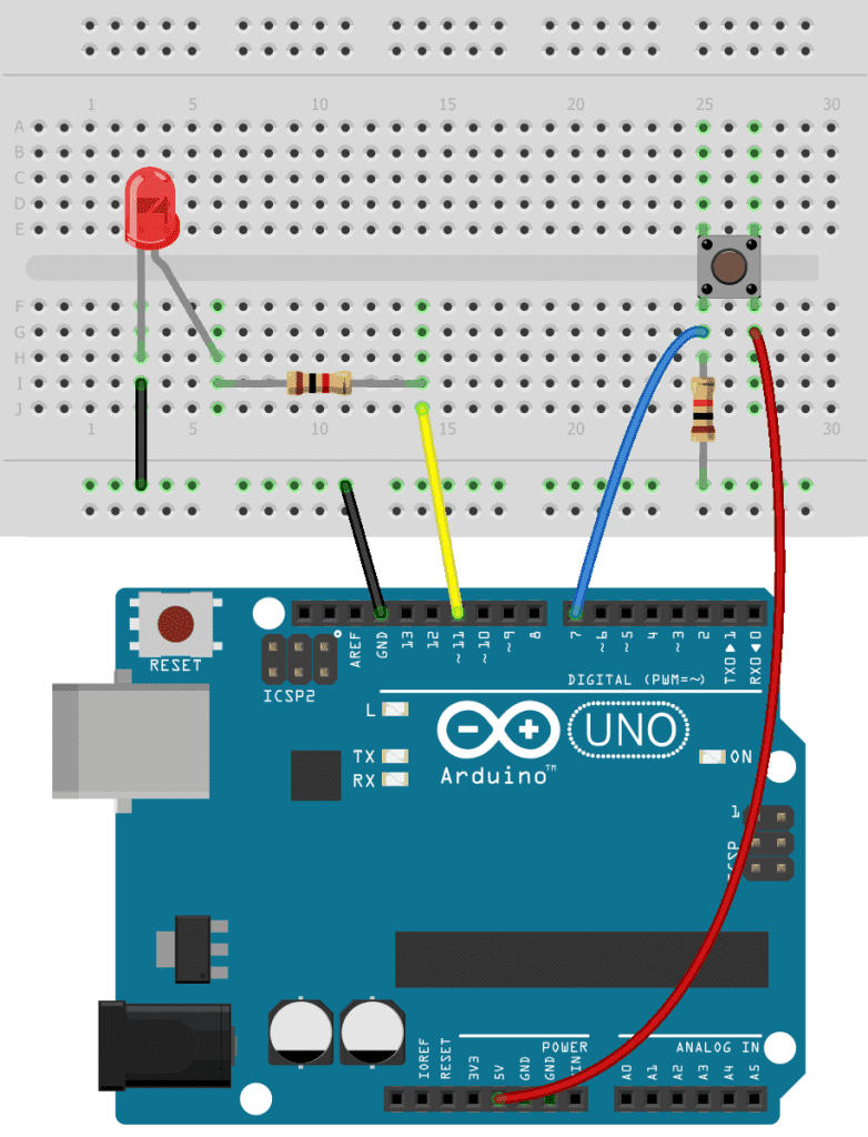
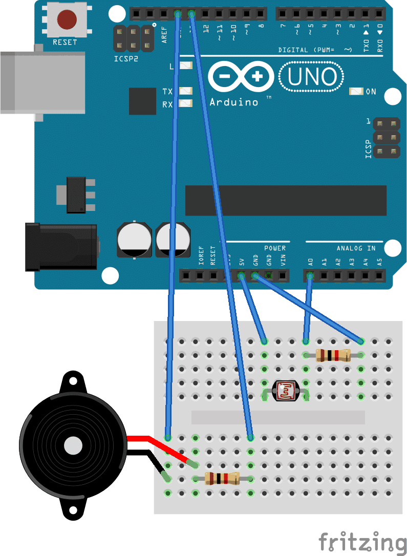
Follow this diagram to connect the circuit:
The current limiting resistor value can be anything from 200 Ohms to 1K Ohms.
One side of the push button is connected to 5 volts, and the other side is connected to pin 7. When the button is pressed, current will flow to pin 7 making it go high. We will use the digitalRead() function to detect when that happens. Then we will use the digitalWrite() function to set pin 11 high, making the LED light up.
How to Program a Push Button on the Arduino
Once you have the circuit connected, upload this code to the Arduino:
int buttonPin = 7;
int ledPin = 11;

void setup() {
  pinMode(buttonPin, INPUT);
  pinMode(ledPin, OUTPUT);
}

void loop() {
  int buttonState = digitalRead(buttonPin);
  digitalWrite(ledPin, buttonState);
}
At the top of the sketch we declare two pin variables. The buttonPin variable will hold the pin number of the Arduino pin connected to the button (pin 7). The ledPin variable will hold the Arduino pin number connected to the LED.
In the setup() section, we use the pinMode() function to set buttonPin as an input. Then we set the ledPin as an output.
In the loop() section, we declare an int variable called buttonState and set it equal to digitalRead(buttonPin). When the button is not pressed, the voltage at the buttonPin will be low, so the digitalRead() function will return a low value. The low value is stored in the buttonState variable. When the button is pressed, the voltage at the buttonPin will be high, so a high value will be stored in the buttonState variable.
We use the digitalWrite() function to send a voltage signal to the LED. The pin we want to send the voltage to is the ledPin so that is the first argument. The second argument of digitalWrite() tells the function to send either a high or low voltage to the pin. But instead of writing high or low, we can use the buttonState variable and the function will write whatever value is stored in that variable to the ledPin.
Floating Pins
If you build the project above and test it, you’ll notice that something weird is going on. The LED will probably flash on and off whenever you move your hand close to the button. What could be causing that?
The Arduino’s digital pins are extremely sensitive. Even weak electromagnetic fields created by your hand can be detected by the Arduino. And those are registered as high signals by the digitalRead() function.
When GPIO pins are allowed to pick up stray electromagnetic fields, they’re called floating pins. We need to fix this by making sure the buttonPin stays low when the button is not pressed. So how can we do that?
Pull Down Resistors
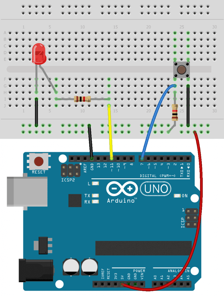
The easiest way is to connect a resistor from the left side of the push button to ground, like this:
When the button is not pressed, stray electromagnetic energy will flow to ground through the resistor. When the button is pressed, the resistor will restrict the current flow to ground and the current will flow to pin 7. This is called a pull down resistor because it connects a pin to ground to keep it in a low voltage state. The value of the pull down resistor can vary, but is usually higher than 10K Ohms.
Pull Up Resistors
Pull up resistors are more common than pull down resistors. Pull up resistors are connected to a voltage source and keep the pin in a high voltage state:
In this circuit, the pull up resistor is connected to 5 volts, and the right side of the button is connected to ground. Pressing the button will send a low signal to pin 7, turning the LED on. The pull up resistor is tied to 5 volts and keeps pin 7 high until the button is pressed.
The code for using a pull up resistor looks like this:
int buttonPin = 7;
int ledPin = 11;

void setup() {
  pinMode(buttonPin, INPUT);
  pinMode(ledPin, OUTPUT);
}

void loop() {
  int buttonState = digitalRead(buttonPin);

  if (buttonState == LOW) {
    digitalWrite(ledPin, HIGH);
  }

  if (buttonState == HIGH) {
    digitalWrite(ledPin, LOW);
  }
}
Similar to the previous program, we declare variables for the buttonPin and ledPin variables and set them as outputs. Then we use the digitalRead() function to detect the voltage state of the buttonPin and store it in the buttonState variable.
We want the Arduino to send a high signal to the ledPin when the buttonState variable is low. In the loop() section, we use two if statements to control what happens when the buttonState variable is high or low. If buttonState is low, the first if statement is executed and the ledPin is written high. If the buttonState variable is high, the program enters the second if statement and a low voltage is written to the ledPin.
So now when you press the button, the LED should turn on and not flicker when you move your hand around the circuit. The floating pin problem is solved.
Arduino’s Internal Pullup Resistor
The pull up and pull down resistors we looked at in this article are external circuit components. But the Arduino also has an internal pull up resistor that you can use for the same purpose. To use the Arduino’s internal pull up resistor, use INPUT_PULLUP as the second argument in the pinMode() function for the buttonPin like this:
int buttonPin = 7;
int ledPin = 11;

void setup() {
  pinMode(buttonPin, INPUT_PULLUP);
  pinMode(ledPin, OUTPUT);
}

void loop() {
  int buttonState = digitalRead(buttonPin);

  if (buttonState == LOW) {
    digitalWrite(ledPin, HIGH);
  }

  if (buttonState == HIGH) {
    digitalWrite(ledPin, LOW);
  }
}
Now you can wire the circuit without the pull up resistor connected to 5 volts. The internal pull up resistor uses one less component and makes the circuit a bit simpler.
Hope this article has helped you to understand the different ways to use a push button for controlling devices with the Arduino. Be sure to leave a comment below if you have any questions!


What about debouncing?
For anyone reading: also look up debounce. When you’re lifting your finger off a button, the Arduino may register multiple presses and you need to account for that. Either via software timer between presses or an analog solution with say capacitors or use a chip dedicated to solving this issue.
Nice explanation of a button and how it can be used in a project but listed equipment states a capacistor and a SN74HC14N Schmitt trigger, what are thous used for?