Making an LED blink is the “hello world” of microcontroller programming. It’s one of the first things to do when learning to program a new microcontroller. An LED is a great way to see what’s happening at the output pins. When the LED lights up, you know the pin it’s connected to is high. The programming concepts used to control an LED are the same concepts used to control a lot of other modules – motors, relays, buzzers, and many sensors are controlled the same way as an LED.

In this article, we will learn how to make LEDs blink on and off, how to control the speed of a blinking LED, and how to control multiple LEDs at the same time. We’ll also learn how to use the pinMode(), digitalWrite(), and delay() functions.
How LEDs Work
Diodes only let electrical current flow in one direction. They’re like a one way valve for electricity. This is the schematic symbol of a diode:

LED are similar to diodes in that they only let current flow in one direction. But LEDs also emit light when current flows through them. LED stands for light emitting diode. This is the schematic symbol of an LED:

LED Polarity
Since current can only flow in one direction, LEDs have polarity. That means they need to be connected the right way around or they won’t work. The side of the LED that connects to a positive voltage is called the anode. The side that connects to ground is called the cathode:
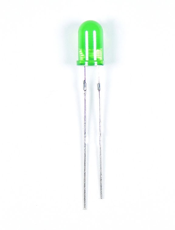
The longer wire is the anode and the shorter wire is the cathode. One side of the LED plastic might be flat, which indicates the cathode side.
LED Brightness
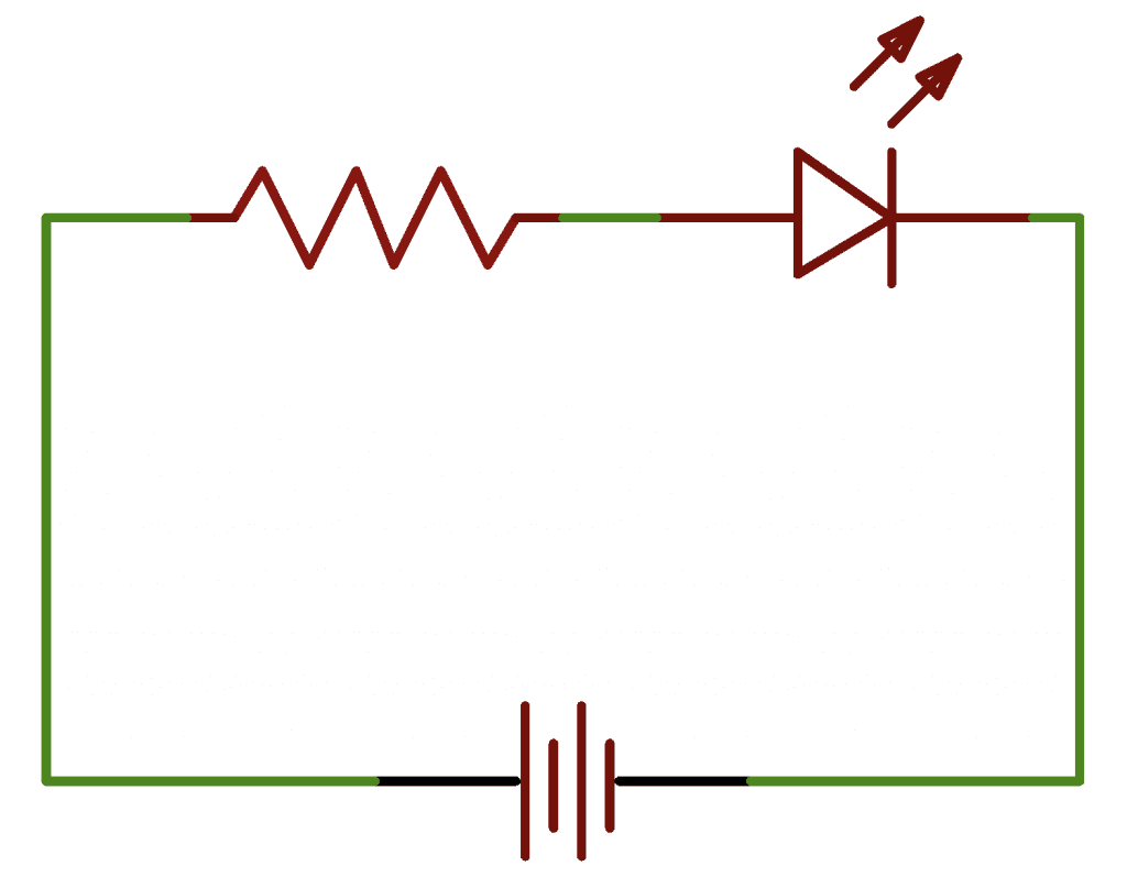
The brightness of an LED is determined by how much current is allowed to flow through it. More current makes the LED brighter, and less current makes it dimmer. But there’s a limit to how much current can flow through an LED. They will quickly burn out if too much current is given to them. To limit the flow of current, we use a current limiting resistor in series with the LED and the power source:
The value of the current limiting resistor affects the brightness of the LED. Higher resistor values restrict the current flow and make the LED dimmer. Lower resistor values allow more current to flow, which makes the LED brighter.
How to Connect an LED to the Arduino
These are the parts you need to connect an LED to the Arduino:
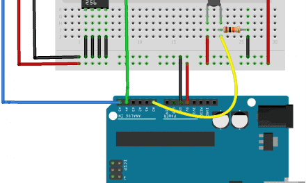
Follow the wiring diagram below to connect the LED and current limiting resistor to the Arduino:
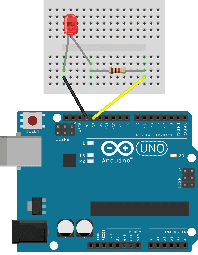
The value of the current limiting resistor can be anything from about 200 Ohms up to about 1K Ohms.
How to Program an LED on the Arduino
Once you have the LED and current limiting resistor connected to your Arudino, upload the code below to the Arduino. This sketch will make the LED turn on for one second, turn off for one second, then repeat:
void setup() {
  pinMode(13, OUTPUT);
}
void loop() {
  digitalWrite(13, HIGH);
  delay(1000);
  digitalWrite(13, LOW);
  delay(1000);
}
Explanation of the Code
First we need to tell the Arduino which pin the LED is connected to and set that pin as an output. For that we use the pinMode() function in the setup() section. The pinMode() function has two arguments – the pin number and the input/output mode:
pinMode(pin, mode);The LED is connected to pin 13 and the pin will be an output pin, so we use:
pinMode(13, OUTPUT);The code in the loop() section will be executed over and over again in a loop. To turn the LED on, we need to send electric current to it. The digitalWrite() function is used to set the voltage state of a digital pin. It two arguments – the pin number and the voltage state (high or low):
digitalWrite(pin, value);For the Arduino, a high voltage level is 5 volts and a low voltage level is 0 volts. To turn the LED on, we write a high voltage to pin 13 like this:
digitalWrite(13, HIGH); Next we need to tell the Arduino how long pin 13 should be high. We do that with the delay() function. The delay() function tells the Arduino to pause and wait before going to the next line of code. The number inside the parentheses is the delay time in milliseconds:
delay(time); We will make the LED blink on and off once every second, so we delay for 1,000 milliseconds:
delay(1000); Now that the LED has been on for one second, we need to turn it off. So we use the digitalWrite() function again, except now we use it to send a low signal to pin 13:
digitalWrite(13, LOW); Then we delay again for 1,000 milliseconds:
delay(1000); You can change how long the LED stays on or off by changing the values in the two delay() functions.
How to Connect Two LEDs to the Arduino
These are the parts you need to connect two LEDs to the Arduino:
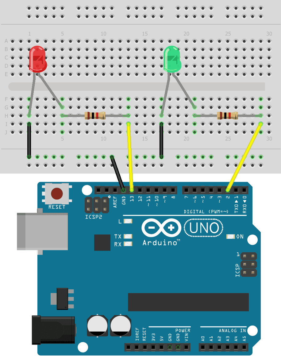
Now that we’ve seen how to connect one LED to the Arduino, let’s add another LED to this circuit. We can add a green LED to go with the red LED. Here’s how to connect the circuit:
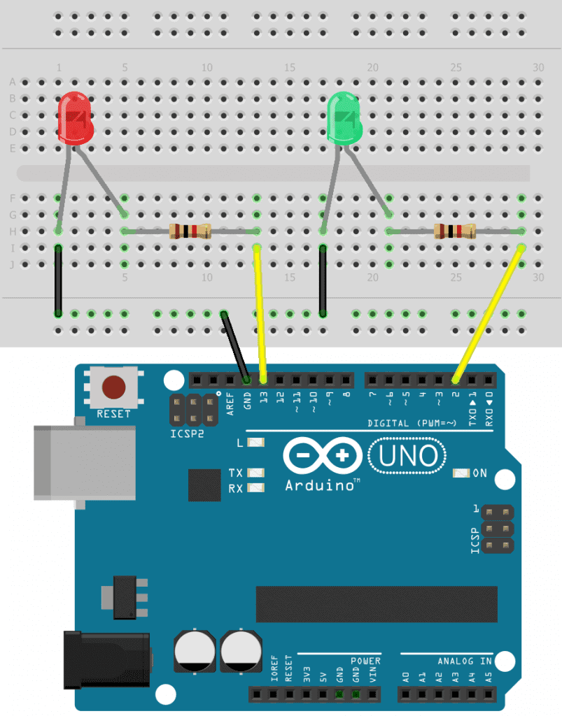
The value of the current limiting resistors can be anything from about 200 Ohms up to about 1K Ohms.
How to Program Two LEDs on the Arduino
To program the two LEDs, we can basically just duplicate the code for a single LED:
int redLED = 13;
int greenLED = 2;

void setup() {
  pinMode(redLED, OUTPUT);
  pinMode(greenLED, OUTPUT);
}

void loop() {
  digitalWrite(redLED, HIGH);
  delay(1000);

  digitalWrite(redLED, LOW);
  delay(1000);

  digitalWrite(greenLED, HIGH);
  delay(1000);

  digitalWrite(greenLED, LOW);
  delay(1000);
}
The only difference here is that we have stored pin 13 in the redLED variable and stored pin 2 in the greenLED variable. These variables are used in the pinMode() and digitalWrite() functions instead of the pin number.
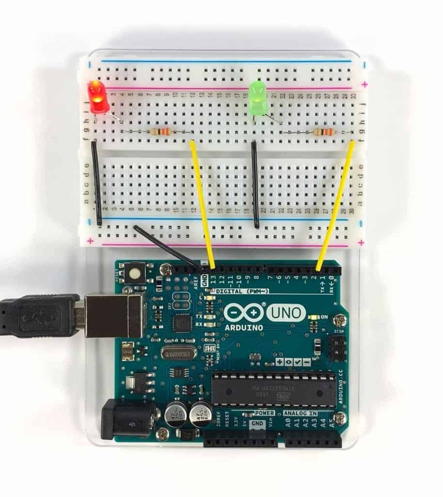
Once you’ve connected the LEDs and uploaded the sketch above, you should see the two LEDs blinking on and off:
Feel free to leave a comment below if you have any questions!


AWESOME PROJECT FOR ME AS STUDENT
Thank you for your informative lesson. First time I come across a real teacher who knows exactly what is expected of him. Sometimes we search and come across “new” programs that we want to learn, but it seems that the clever people always assumes that we are all equally clever. Thank you for filling that gap for me. I will use your material to advance and enhance my Arduino skills.