
Passive infrared (PIR) sensors can detect infrared radiation that is emitted by warm objects like humans and animals. PIR sensors are commonly used in home security systems and as sensors to activate interior lighting when a person enters a room. They can also be used to activate video cameras when a person or animal comes within range of the sensor.

In this article we will see how to setup a PIR sensor on the Arduino, and use the sensor’s input to control a 5V relay.
Watch the video for this tutorial here:
Overview of a Passive Infrared Sensor
The PIR sensor we will use in this article is the HC-SR501 passive infrared sensor:
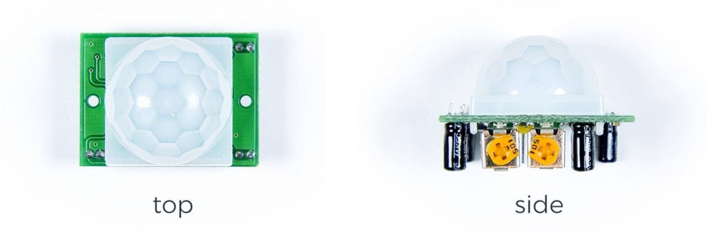
The white plastic dome on top of the sensor is a lens. The lens widens the sensor’s field of view so it can detect motion from a wider angle. The lens extends the sensing area to a 110 degree cone in front of the sensor. Underneath the lens is the infrared sensing element:
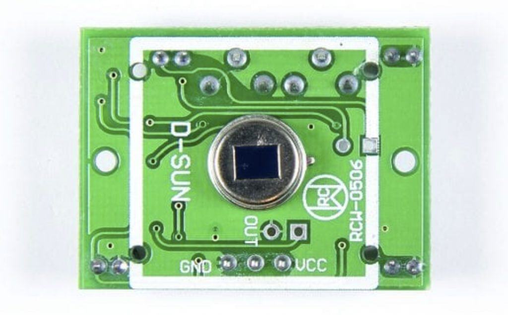
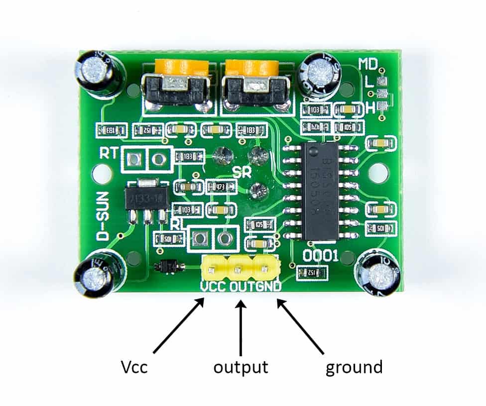
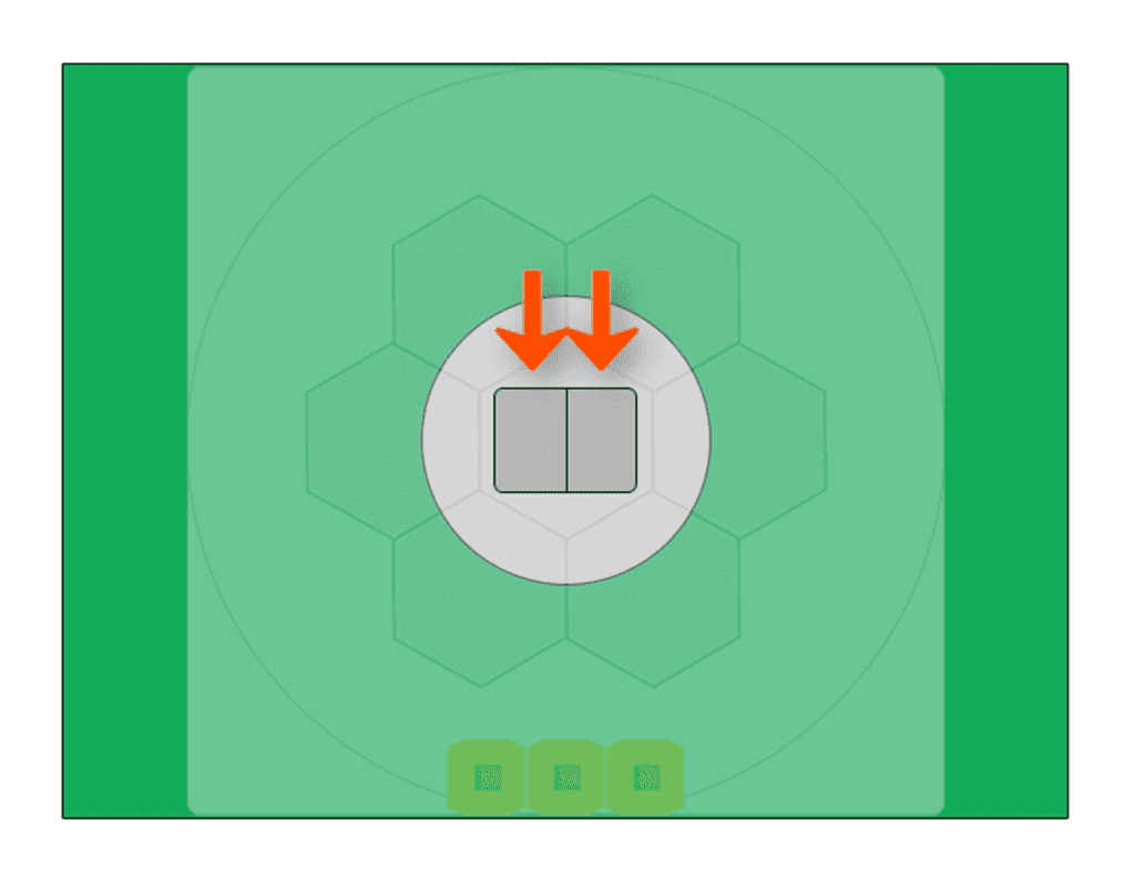
The sensing element is a pyroelectric infrared sensor. We’ll get a closer look at how it works in a minute. The HC-SR501 only has three pins – Vcc, output, and ground:
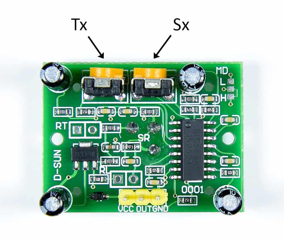
When the sensor detects motion it outputs a HIGH signal. The duration of the HIGH output can be adjusted by turning the Tx potentiometer. The shortest time is about 3 seconds and the longest is about 5 minutes. Turning the potentiometer clockwise increases the time and turning it counter-clockwise decreases the time.
The sensitivity, or range, of the sensor is adjusted with the Sx potentiometer. The sensor can detect motion in a range from as close as 2 meters up to 7 meters. Turning the Sx potentiometer clockwise decreases the range and turning it counter-clockwise increases the range.
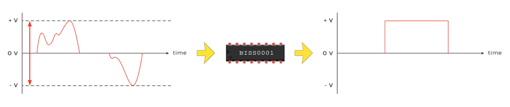
The 16 pin IC in the image above is the control chip for the module, the BISS0001. The BISS0001 takes the analog output from the sensing element and converts it into a digital signal.
How PIR Sensors Work
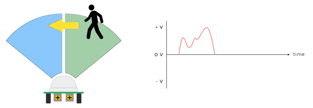
PIR sensors like the HC-SR501 detect motion by measuring changes in infrared radiation across the sensor. The sensor element actually has two separate sensing elements:
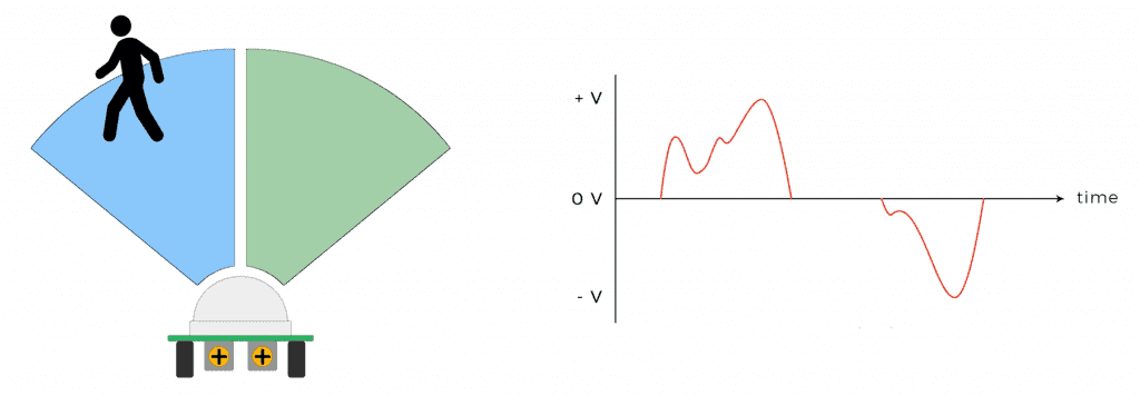
The two sensing elements allow the sensor to differentiate between static sources of IR light like sunlight, and moving sources like humans and animals. When an IR emitting object crosses the path of the sensor, the first element measures the IR light and generates a HIGH signal.
When the object crosses the path of the second element, it generates a LOW signal.
When the BISS0001 detects a large difference between the signals from the two sensing elements, it outputs a HIGH signal:
How to Use a PIR Sensor to Activate a 5V Relay
One useful application of PIR sensors is to turn on a light when a person enters a room. 5 volt relays can control high voltage power sources so that lights and appliances can be switched on and off with the output from a sensor.
In this project, we will use the output of a PIR sensor to control a 5 volt relay. We won’t go into detail about 5 volt relays, but if you want to learn more check out our article on Setting up a 5V Relay on the Arduino.
Here are the parts you will need:
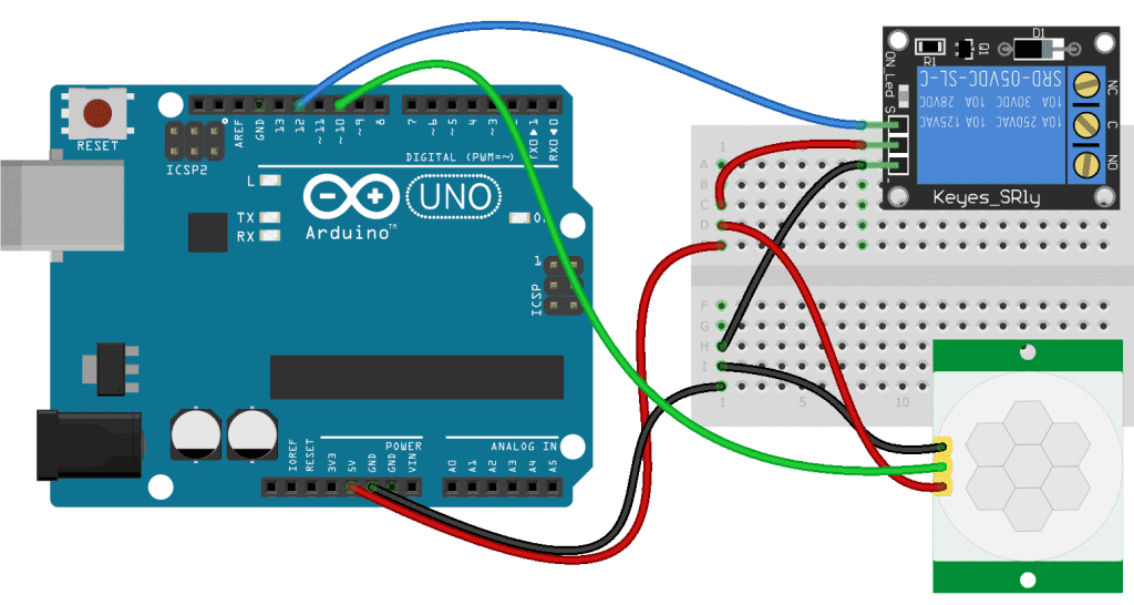
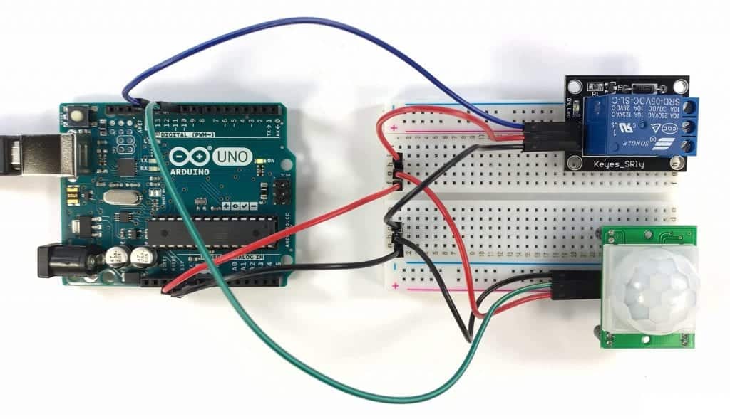
Follow the diagram below to connect the PIR sensor and 5V relay to the Arduino:
WARNING!!! DO NOT CONNECT ANY HIGH VOLTAGE DEVICES TO THIS CIRCUIT UNLESS YOU HAVE EXPERIENCE WORKING WITH SUCH DEVICES. MISTAKES WITH HIGH VOLTAGES COULD LEAD TO FIRE, INJURY, OR EVEN DEATH.
Once the circuit is connected, upload this code to the Arduino:
int sensorPin = 10;
int relayPin = 12;

void setup() {
  pinMode(sensorPin, INPUT);
  pinMode(relayPin, OUTPUT);
}

void loop() {
  int value = digitalRead(sensorPin);

  digitalWrite(relayPin, value);
}
Explanation of the Code
First we declare an int variable called sensorPin and set it equal to digital pin 10. This variable will store the output from the PIR sensor. Next we declare a variable called relayPin and set it equal to digital pin 12. This variable will store the value used to control the input pin on the 5V relay.
In the setup() section, we set the pin mode of the sensorPin to INPUT and the pin mode of the relayPin to OUTPUT.
In the loop() section, we take a digital read of the sensorPin and store the result in a local variable called value. Then we digital write the relayPin with the value stored in the value variable.
So when the output of the PIR sensor is HIGH, which means that motion is detected, the relay pin will be written HIGH as well. That will activate the relay, and turn on whatever is connected to it. After everything is connected and the sketch is uploaded to the Arduino, wave your hand in front of the PIR sensor:
You should hear the relay click and see the relay’s LED turn on. The relay will stay activated for the length of the PIR sensor’s time delay. If you’re using this for a motion activated light, use a longer time delay. That way the PIR sensor will keep getting triggered while people are in the room, so the light will stay on the whole time.
Thanks for reading! Just leave a comment below if you have any questions…

great innovative idea very usefull for beginnior.
thanks a lots.