A multimeter is an electronic measuring instrument that has multiple functionalities, hence it is also called a multitester. Typically, these functionalities include the ability to measure voltage, current, and resistance. This measurement tool is essential for troubleshooting because it can measure with a very high degree of accuracy. This device, with a positive and a negative indicator, is a useful tool that helps users, from simple tests, faults detection, to complex diagnostics. A multimeter is a must-have for electricians, engineers, and even for students of electronics and electricals. They come in analog and digital versions. These are available in a wide range of features and prices.

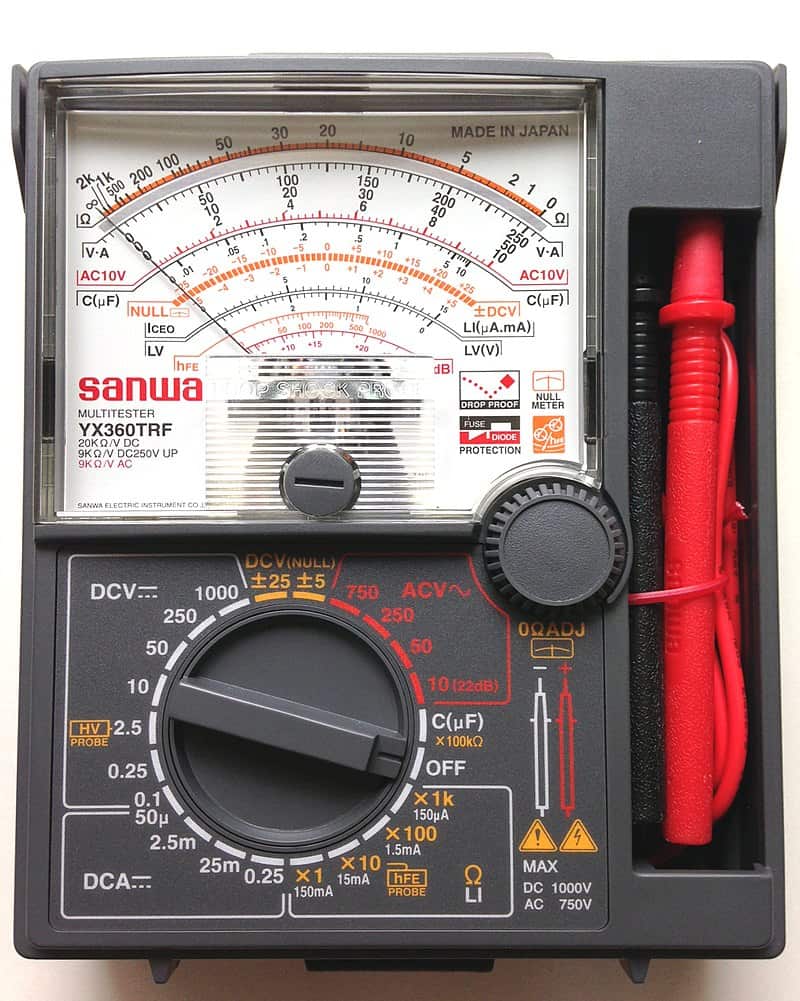
Analog Multimeter
An analog multimeter is one of the old devices which uses the D-Arsonal movement in performing measurements. Though the greater majority of people today use digital multimeters, this does not necessarily mean that analog multimeters are no longer popular. Analog multimeters are great for detecting slow voltage changes because you can watch the needle moving over the scale. Analog testers are exceptional when set as ammeters due to their low resistance and high sensitivity.
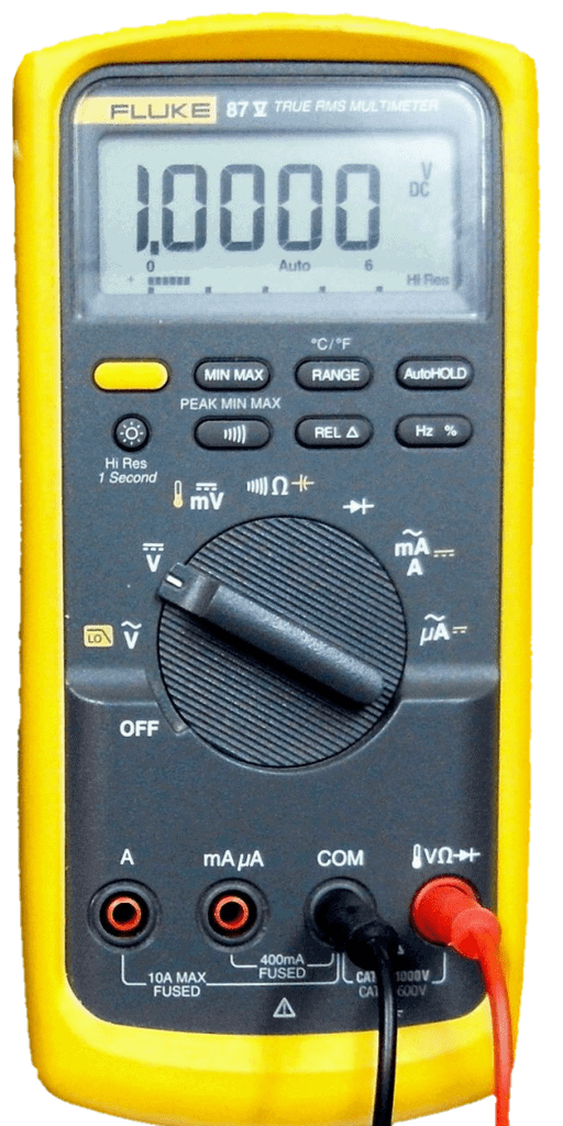
Digital Multimeter
Digital multimeters have been more commonly used nowadays. They are the digital counterparts of analog multimeters. This device has taken over the analog and is popular for several reasons. It displays the readings in digits through a LED or LCD screen. It also provides accurate results and is portable and easy to carry. Its automatic calibration made it also the more popular choice in the industry.
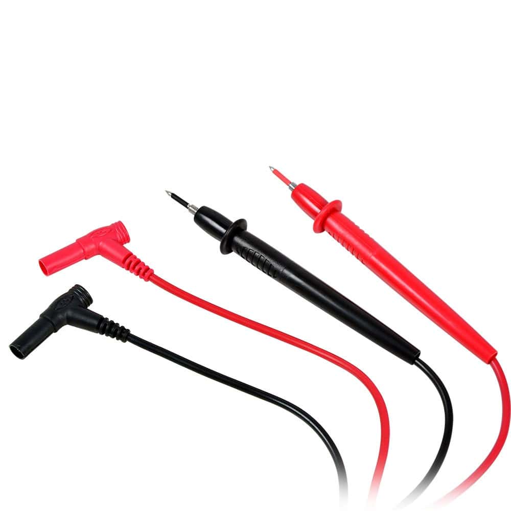
Below are probes that come along and are connected to multimeters.
Analog Multimeters vs. Digital Multimeters
Analog and digital multimeters are both measuring devices that can measure resistance, current, and voltage. As described above, the most obvious difference between a digital and an analog multimeter is the display. But there’s a lot more!
Here are some comparable qualities of the two:
| Analog Multimeter | Digital Multimeter | |
| How it works | Uses a Galvanometer when measuring current. | Uses Analog to Digital Converter (ADC) when measuring voltage. |
| Ability to measure | Measures the basic qualities such as resistance, current and voltage. | Measures the basic and advance qualities such as resistance, current, voltage, capacitance, inductance. It can also check if a diode or transistor is faulty or not. |
| Accuracy | The possibility of misreading measurements is higher. | Gives accurate readings displayed as exact numerical values. |
| Range | Set manually by rotating the knob. | Has auto-ranging features |
| Frequency Range | Only up to 2kHz | Can measure higher frequency ranges |
| Reverse Polarity | Pointer deflects to the left | Indicates a negative quantity |
| Size | Bigger | Smaller |
| Cost | Less costly | More expensive |
| Calibration | Manual | Automatic |
| Power Supply | Not required | Required |
| Usability | Difficult | Easier |
Auto-Ranging
Auto-ranging is a special feature of a digital multimeter. It is one great advantage of digital multimeters because it saves you from the hassle of manually setting the range of values for resistance, current, voltage, or whatever electrical characteristic you want to measure. The digital multimeter finds these values for you. Multimeters with the auto-ranging feature are more expensive but well worth the price. With this feature, the user just simply needs to switch the notch to ohmmeter and the multimeter will then display the digital value of the resistance reading.
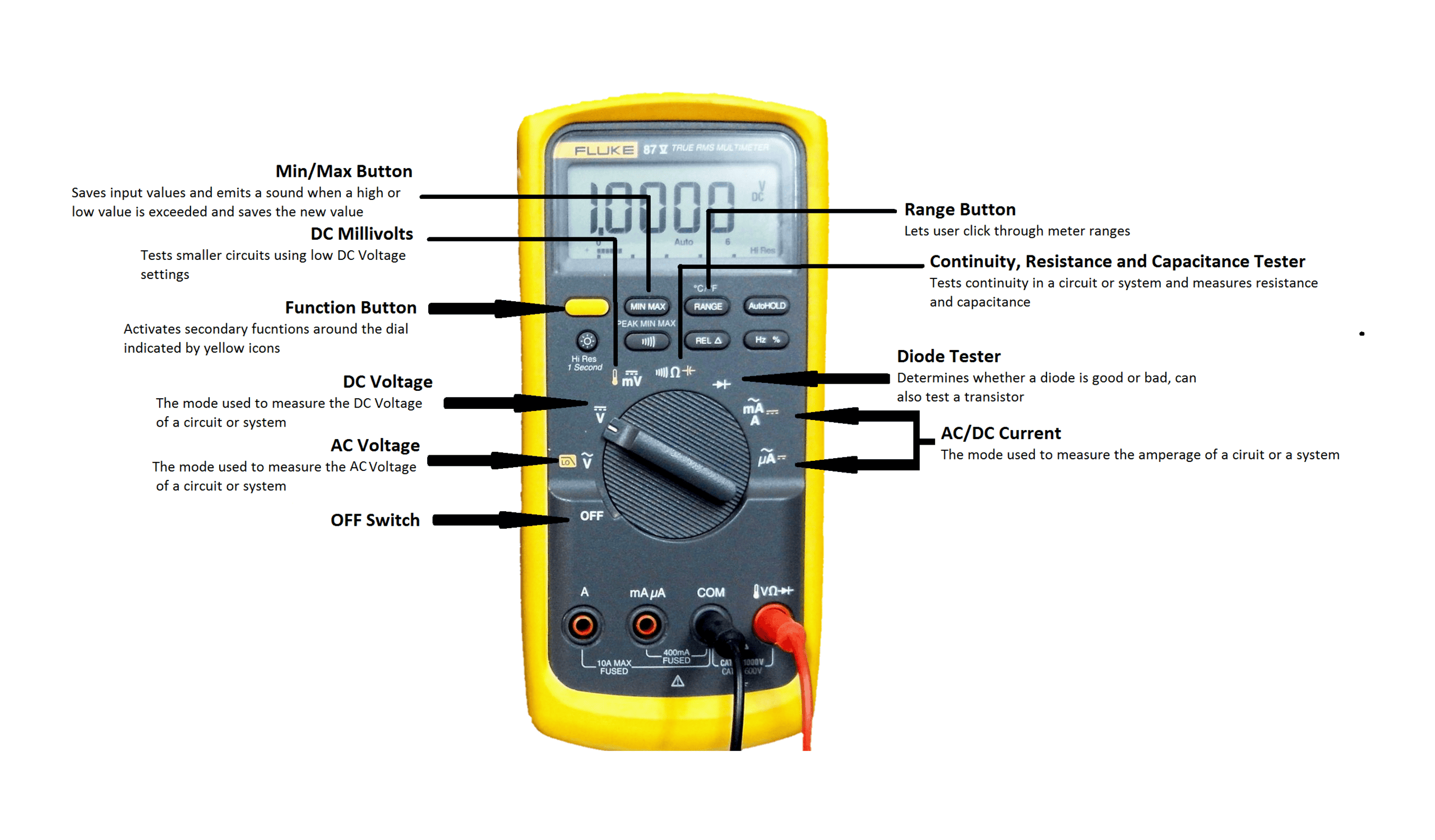
Multimeter Modes and Functions
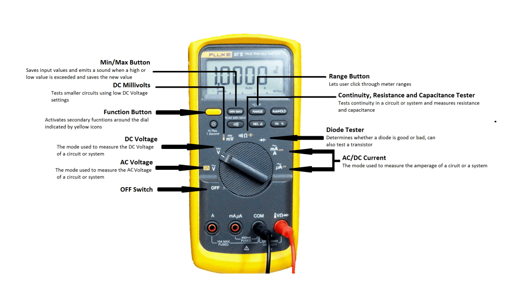
How to Use a Digital Multimeter
Measuring AC Voltage
- Connect the probes to their corresponding slots– the black probe to the “COM” or common slot, which is the ground, and the red probe to the “VΩ” slot.
- Turn the knob to the AC Voltage sign, the letter V with this sign ~ above it.
- Connect the black probe to the circuit.
- Connect the red probe to the circuit.
- Read the result on the screen.
Measuring DC Voltage
- Connect the probes to their corresponding slots– the black probe to the “COM” or common slot, which is the ground, and the red probe to the “VΩ” slot.
- This time, turn the knob to the DC Voltage sign, the letter V with a line above it.
- Connect the red probe to the positive terminal.
- Connect the black probe to the negative terminal.
- Read the result on the screen.
Measuring AC Current
- Connect the probes to their corresponding slots– the black probe to the “COM” or common slot, which is the ground, and the red probe to the “VΩ” slot.
- Turn the knob to the AC Current sign, the letter A with the sign ~ above it.
- Connect the probes to both ends of the circuit.
- Read the result on the screen.
Measuring DC Current
- Connect the probes to their corresponding slots– the black probe to the “COM” or common slot, which is the ground, and the red probe to the “VΩ” slot.
- Turn the knob to the DC Current sign, the letter A with a line above it.
- Connect the probes to both ends of the circuit.
- Read the result on the screen.
Measuring Resistance
- Connect the probes to their corresponding slots– the black probe to the “COM” or common slot, which is the ground, and the red probe to the “VΩ” slot.
- Select the required range.
- Touch the probes to the ends of the resistor.
- Read the display on the screen.
Measuring Capacitance
- Turn the knob to capacitance testing mode– with the icon or symbol of a capacitor.
- Connect the probes to the capacitor ends.
- If polarized, determine the positive and negative sides.
- Read the result on the screen.
Continuity
It is the presence of a complete path for the flow of current. If there is no continuity, it means that there is a break somewhere in the circuit. It will then produce no sound or tone in the digital multimeter. On the other hand, if two points are connected electrically, or are continuous, the digital multimeter will emit a sound or tone. This test ensures that there is a connection between two points.
Continuity is one of the most useful tests for electronics repair. Continuity tests are of utmost importance in avoiding fires, shocks, or damages to electrical devices.
Now, how to check continuity?
- Turn off the system, unplug it, or remove the batteries.
- Connect the probes to their corresponding slots– the black probe to the “COM” or common slot, which is the ground, and the red probe to the “VΩ” slot.
- Turn the knob to continuity mode with the icon or symbol like that of sound waves.
- To check if the continuity calibration of the multimeter works, touch the metal end of the probes together. If the number on the screen displays less than 1 or 0, then the multimeter is functioning properly. This will then indicate continuity, and the digital multimeter must emit a sound or a tone.
- Place the probes at each end of the circuit or component you want to test. If the result is the same to step 4 then there is continuity in the circuit or the component.
Testing Transistors and Diodes
Transistors
- Connect the probes to their corresponding slots– the black probe to the “COM” or common slot, which is the ground, and the red probe to the slot or terminal with the diode sign.
- Turn the knob to the diode tester.
- Connect alligator clamps to both metal end of the two probes.
- Determine which of the transistor leads is the collector, base, and emitter.
- Clamp the probes to the transistor leads– the black probe to the base of the transistor and the red probe to the emitter.
- Read the display on the multimeter and take note of the resistance.
- Remove the red probe from the emitter and move it to the collector side.
- The display on the multimeter should be the same as when the red probe was on the emitter side.
- Remove the black probe from the base side.
- Clamp the red probe to the base side.
- Clamp the black probe to the emitter side. Take note of the displayed value.
- Clamp the black probe to the collector side. Take note of the displayed value.
- If both previous readings (when the black probe is at the base) are higher than the current readings (when the red probe is at the base), the transistor is good.
- If both previous readings are lower than the current readings, the transistor is good.
- If it is neither steps 13 and 14, then the transistor is bad.
Diodes
- Connect the probes to their corresponding slots – the black probe to the “COM” or common slot, which is the ground, and the red probe to the slot or terminal with the diode sign.
- Turn off the power source.
- Turn the knob to the diode tester.
- Determine the cathode and the anode of the diode. Touch the anode using the red probe and the cathode using the black probe.
- Read the display on the multimeter. If the reading is between 0.5 to 0.8V, then the diode is good. Otherwise, it’s not.
- Switch the black probe and the read probe.
- Read the display on the multimeter. If the reading is zero, then the diode is good. Otherwise, it’s not.
Hope this article has helped you to learn more about multimeters and how to use them for your own project. If you have any questions, feel free to leave a comment below.

Thanks for sharing how to use a multimeter.
circuit basic is doing well for the engineers like me. I am grateful