In 1996, there were several countries involved in the development of short-range wireless links, and together they wanted some unification of standards and a name that symbolized unity. Intel, Ericsson, and Nokia were involved, and the name Bluetooth was suggested to symbolize unity. In the 10th century, King Harold the Bluetooth was responsible for unifying Scandinavia. The name wasn’t meant to be permanent, but it stuck.

Bluetooth was created to exchange data within short range without the need for wires like headphones, heart monitors, and sensors. It works in the ISM 2.4GHz band. Data is split into one of 79 slots between 2.4 and 2.4835 GHz in 1MHz bands. Bluetooth LE (Low Energy) was a new version. Unlike the earlier standard Bluetooth, LE requires no contracts or problems with developing apps, and you can distribute via the Play Store; it also requires very little power, so it is very suitable for battery operation.
Arduino Bluetooth Options
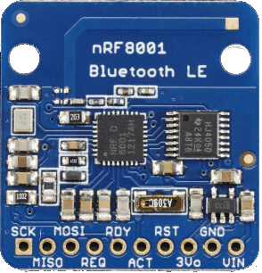
While a handful of Arduino boards have Bluetooth built-in, some projects may require the use of external Bluetooth modules. The HC-05 Bluetooth transceiver module is the most common Bluetooth transceiver, but it has high power consumption and can’t be linked to smartphones. Instead we will use the nRF8001 Bluetooth module which has a lower power consumption and can be connected to smartphones.
Project Overview
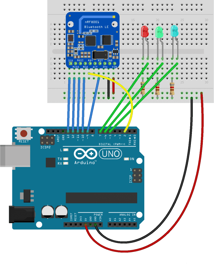
We are going to connect an Arduino UNO to the nRF8001 module and send and receive data to/from it as though it were a serial port. In other words, we will use the built-in ability to act as a UART. We will add a red, green, and blue LED, and by sending an ‘r’ or ‘b’ or ‘g’, we will pulse that LED for a few mS. We will also type in strings at the serial console, and send these back to the cell phone.
Note: I have only tested all this on an Android phone (Samsung Galaxy J3)
How the nRF8001 Works
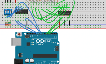
One of the cool features of the nRF8001 is that its interface to the user is a UART. In other words, plain old serial Tx and Rx, which makes it very easy to use. The first three pins on the PCB are the SPI interface, SCK is just a clock, MISO is Master In Slave Out, and MOSI is Master Out Slave In. These four pins must go to the Arduino as shown and are not negotiable. REQ signals to the nRF that the Arduino has something to say and RDY tells the Arduino that the nRF has something to say and must go to one of the Arduino’s interrupt request pins, i.e., 2 or 3. RST is the reset pin and resets the nRF at startup. REQ is used similarly to SS that you may have come across in other SPI applications. Adafruit has more details on its nRF8001 here.
How to Connect the nRF8001 to the Arduino
Here are the parts you will need to build this project:
If you want to learn more about the Arduino, check out our Ultimate Guide to the Arduino video course. You’ll learn basic to advanced Arduino programming and circuit building techniques that will prepare you to build any project.
Install the Library
There is only one library required – the SPI library that is automatically installed with the Arduino IDE. But if you don’t have it, you can download it here.
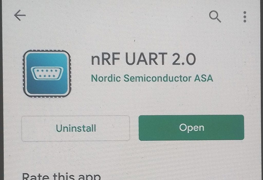
You will also need to download and install Nordic’s Android nRF UART 2.0 application from the Play Store on your Android phone. I don’t have an iPhone to test it, but it should work on Apple devices too.
Notes on the Program
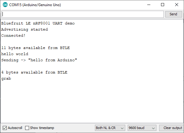
Although the nRF8001 is a 3.3V device, the Vcc and data pins are 5V tolerant so you can use either. The sketch to demonstrate the project is based on the example provided in the library under “examples” as “echodemo”. Once you have loaded the design and opened the serial window, you should see something like this on your cellphone:
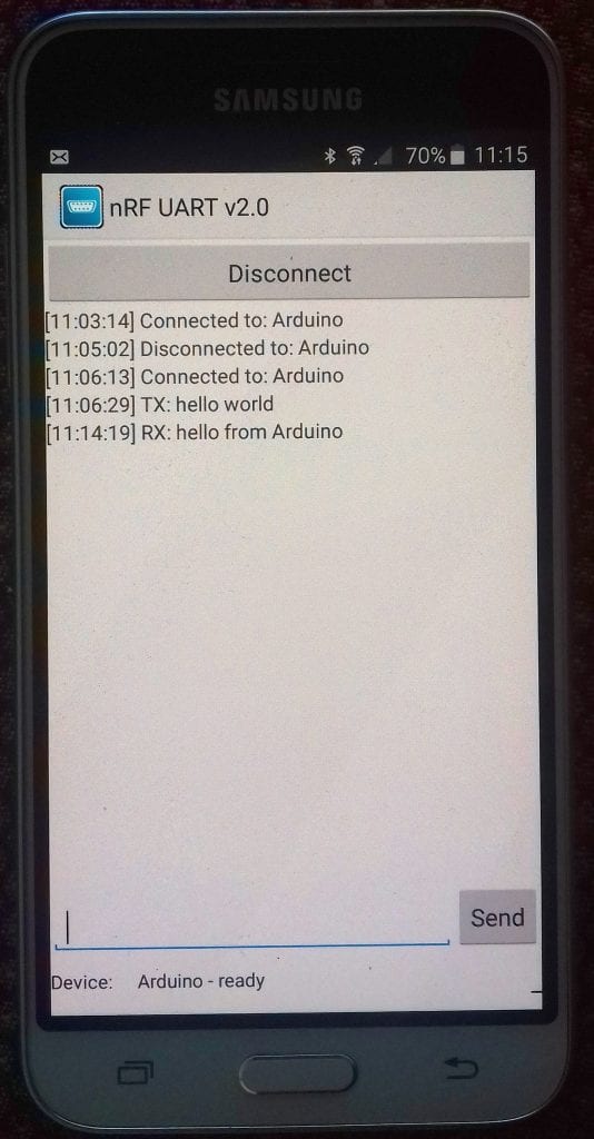
Type in some text and hit the Send button. The text should appear in the Arduino’s serial monitor. Enter text on the serial window and send it, and it will appear on your phone.
In the modified example below, I have added a red, green, and blue LED to the board, and you can flash these by entering an r, or b or g from the phone. Typing a word with all three such as “grab” will flash all three. My phone is an older Samsung Galaxy and worked just fine.
Arduino Code
Once the circuit is connected, upload this code to the Arduino:
  //an adaptation of the "echodemo" example in the library examples folder
  #include <SPI.h>
  #include "Adafruit_BLE_UART.h"
  //On UNO & compatible: CLK = 13, MISO = 12, MOSI = 11
  #define BLE_REQ 10
  #define BLE_RDY 2 // This should be an interrupt pin, on Uno thats #2 or #3
  #define BLE_RST 9
  Adafruit_BLE_UART BTLE = Adafruit_BLE_UART(BLE_REQ, BLE_RDY, BLE_RST);
  #include <LiquidCrystal_I2C.h>
  #define  BL_ON  1
  #define  BL_OFF  0
  #define ADDRESS 0x38
  LiquidCrystal_I2C lcd(ADDRESS, 16, 2);  // set the LCD I2C address
  byte blueLED = 3;
  byte redLED = 5;
  byte greenLED = 4;
  aci_evt_opcode_t laststatus = ACI_EVT_DISCONNECTED;

  void setup(void)
  {
  lcd.init();     // initialize the lcd
  lcd.setBacklight(BL_ON);
  lcd.setCursor(0,0); //col, row
  lcd.print("Bluetooth tests ");
  Serial.begin(9600);
  Serial.println(F("Bluefruit LE nRF8001 UART demo"));
  BTLE.setDeviceName("Arduino"); /* 7 characters max! */
  BTLE.begin();

  pinMode(blueLED, OUTPUT);
  pinMode(redLED, OUTPUT);
  pinMode(greenLED, OUTPUT);

  //pre test flash LEDs:
  digitalWrite(redLED, HIGH);
  delay(200);
  digitalWrite(redLED, LOW);
  delay(200);
  digitalWrite(greenLED, HIGH);
  delay(200);
  digitalWrite(greenLED, LOW);
  delay(200);
  digitalWrite(blueLED, HIGH);
  delay(200);
  digitalWrite(blueLED, LOW);
  delay(200);
  }

void loop()
{
  // Tell the nRF8001 to do whatever it should be working on.
  BTLE.pollACI();
  // Ask what is our current status
  aci_evt_opcode_t status = BTLE.getState();

  // If the status changed....
  if (status != laststatus)
    {
    // print it out!
    if (status == ACI_EVT_DEVICE_STARTED) {
    Serial.println(F("Advertising started"));
    }
    if (status == ACI_EVT_CONNECTED)
      {
      Serial.println(F("Connected!"));
      }
    if (status == ACI_EVT_DISCONNECTED)
      {
      Serial.println(F("Disconnected or advertising timed out"));
      }
    // OK set the last status change to this one
    laststatus = status;
    }

  if (status == ACI_EVT_CONNECTED)
    {
    // Lets see if there's any data for us!
    if (BTLE.available())
      {
      Serial.println();
      Serial.print(BTLE.available()); //gets number of bytes available
      Serial.println(F(" bytes available from BTLE"));
      }
    // OK while we still have something to read, get a character and print it out
    //lcd.clear();
    lcd.setCursor(0,1); //col, row
    while (BTLE.available())
      {
      char c = BTLE.read();
      Serial.print(c);

      lcd.write(c);
      if(c == 'r')
        {
        digitalWrite(redLED, HIGH);
        delay(800);
        digitalWrite(redLED, LOW);
        }
      if(c == 'g')
        {
        digitalWrite(greenLED, HIGH);
        delay(800);
        digitalWrite(greenLED, LOW);
        }
       if(c == 'b')
        {
        digitalWrite(blueLED, HIGH);
        delay(800);
        digitalWrite(blueLED, LOW);
        }
       if(c == 'c')
        {
        lcd.setCursor(0,1); //col, row
        lcd.print("                "); //clear 2nd line
        }
      }
    // Now see if we have any data from Arduino keybd/Serial console
    if (Serial.available())
      {
      // Read a line from Serial
      Serial.setTimeout(100); // 100 millisecond timeout
      String s = Serial.readString();
      // We need to convert the line to bytes, no more than 20 at this time
      byte sendbuffer[20];
      s.getBytes(sendbuffer, 20);
      char sendbuffersize = min(20, s.length());
      Serial.print(F("\nSending -> \""));
      Serial.print((char *)sendbuffer);
      Serial.println("\"");
      // write the data:
      BTLE.write(sendbuffer, sendbuffersize);
      }
    }
  }
Output of the Serial Monitor
Now open the serial monitor and you should see
Thanks for reading and be sure to let us know if you have any questions in the comment section below.


