It probably won’t take long working with the Arduino before you will find a need to use hardware or timer interrupts. Interrupts can help when you want the Arduino to do more than one thing at a time. Interrupts will make the Arduino stop what it’s doing to perform another task. Once the task is finished, the Arduino will resume what it was doing before being interrupted.

In this article, we’ll learn how to use two different types of interrupts, hardware interrupts and timer interrupts. Hardware interrupts are triggered by an external event like the press of a button or a signal from a sensor. Timer interrupts are triggered by one of the Arduino’s internal timers.
But before we begin, let’s first see an example of why interrupts are useful.
Watch the video for this tutorial here:
Blinking LEDs Without Interrupts
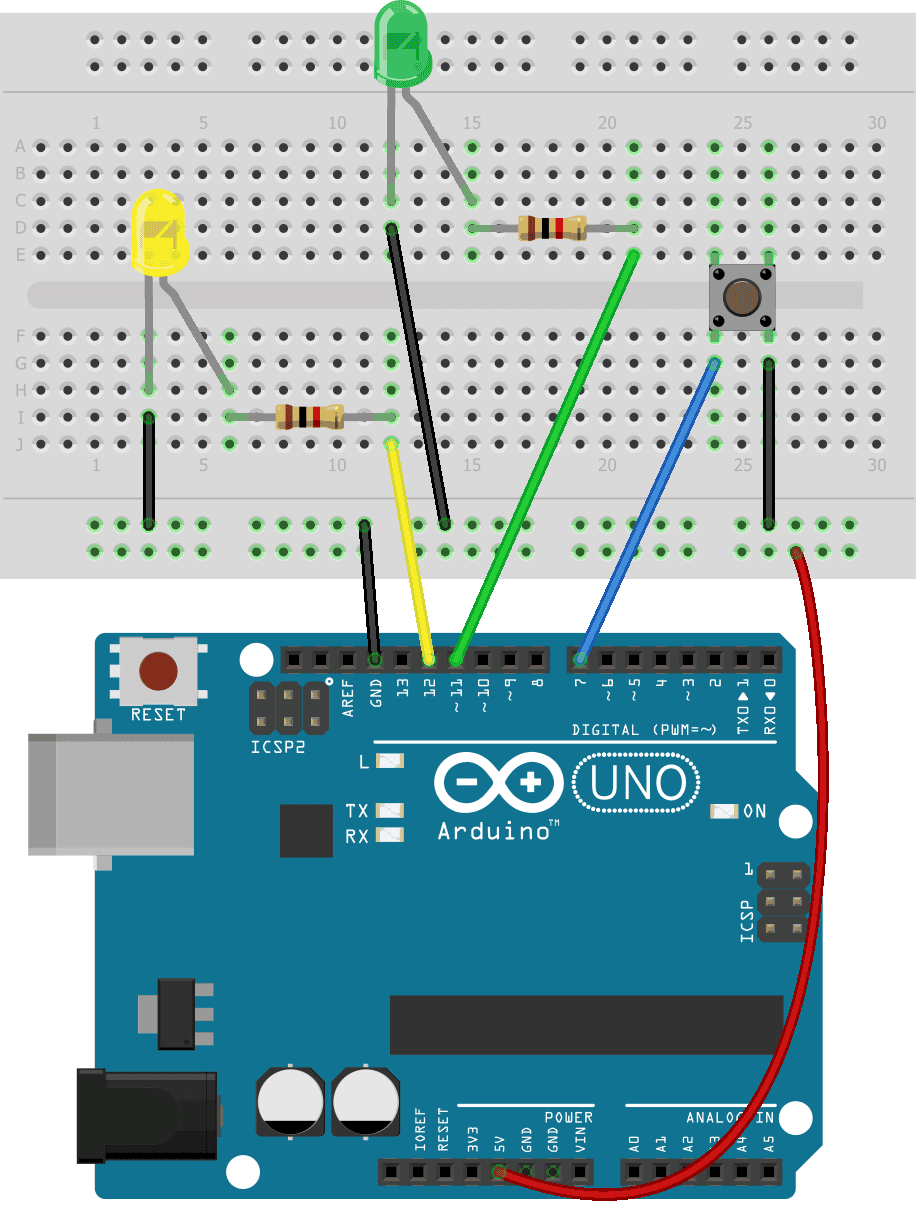
Let’s build an example project that attempts to control a blinking LED with a push button. In the circuit below, the yellow LED will blink on and off repeatedly. The green LED will turn on when you push the button.
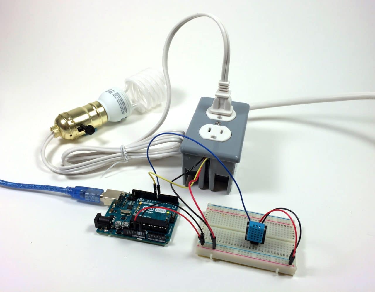
These are the parts needed to build the project:
Connect the circuit following this wiring diagram:
Here is the code for the circuit:
int buttonPin = 7;
int buttonLED = 11;
int blinkLED = 12;

void setup() {
  pinMode(buttonPin, INPUT_PULLUP);
  pinMode(buttonLED, OUTPUT);
  pinMode(blinkLED, OUTPUT);
}

void loop() {
  int buttonState = digitalRead(buttonPin);

  if (buttonState == HIGH) {
    digitalWrite(buttonLED, LOW);
  }

  if (buttonState == LOW) {
    digitalWrite(buttonLED, HIGH);
  }

  digitalWrite(blinkLED, HIGH);
  delay(200);
  digitalWrite(blinkLED, LOW);
  delay(200);
}
If you build this project, you’ll see that the yellow LED blinks on and off just fine. But when you press the button, the green LED will turn on sometimes but it misses a lot of the presses. When the Arduino gets to one of the delay() functions, it pauses and can’t do anything else until the delay is over so it misses some of the button presses. Let’s fix this problem by using a hardware interrupt.
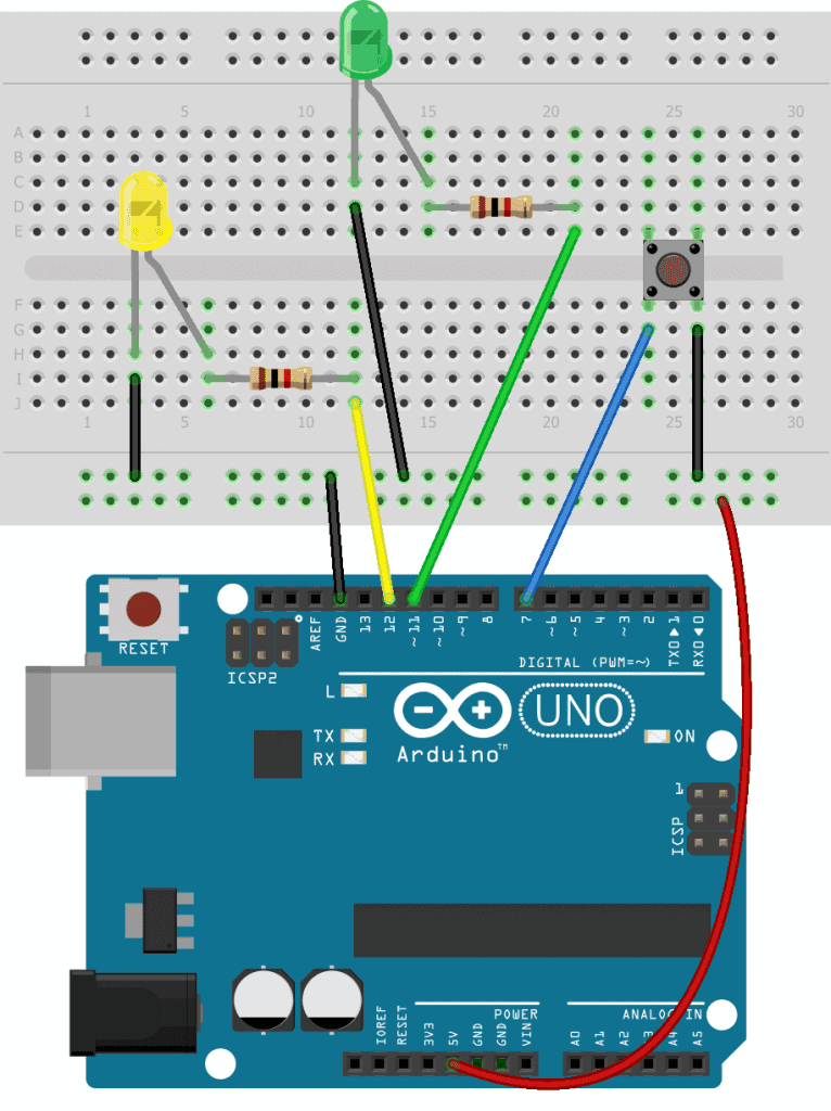
How to Make a Hardware Interrupt
The sketch below adds a hardware interrupt to the blinking LED sketch above, so that every button press is detected by the Arduino:
int buttonPin = 2;
int buttonLED = 11;
int blinkLED = 12;
volatile int buttonState;

void buttonInterrupt() {
  buttonState = digitalRead(buttonPin);
  if (buttonState == HIGH) {
    digitalWrite(buttonLED, LOW);
  }
  if (buttonState == LOW) {
    digitalWrite(buttonLED, HIGH);
  }
}

void setup() {
  pinMode(buttonPin, INPUT_PULLUP);
  pinMode(buttonLED, OUTPUT);
  pinMode(blinkLED, OUTPUT);
  attachInterrupt(digitalPinToInterrupt(buttonPin), buttonInterrupt, CHANGE);
}

void loop() {
  digitalWrite(blinkLED, HIGH);
  delay(200);
  digitalWrite(blinkLED, LOW);
  delay(200);
}
To make an interrupt, you first need to write a special function called an interrupt service routine (ISR). The interrupt service routine will contain all of the code you want to be executed when the interrupt is triggered. In the blinking LED example from earlier, we wanted the button presses to control the green LED while the yellow LED was blinking on and off. So the logical choice would be to have the button presses trigger the interrupt.
In the sketch above, there is an ISR for the button presses called buttonInterrupt(). Inside the ISR is the code that reads the buttonPin and switches the green LED on and off.
Interrupt Service Routines
Interrupt service routines contain the code you want executed when the interrupt is triggered. The code should be as short and fast as possible. If you use multiple interrupts, be aware that only one interrupt can be run at a time.
The millis(), micros(), and delay() functions all depend on interrupts themselves, so they won’t work inside of an interrupt service routine. However, if you need a delay in your ISR, you can use the delayMicroseconds() function to achieve the same effect. Also, Serial.print() doesn’t always work inside an ISR because data is transferred to the serial monitor with an interrupt. Interrupt service routines can’t take inputs or return values.
If you have any variables in the ISR, like the one for buttonState, it should have the volatile keyword in front of it. Declaring a variable as volatile prevents the compiler from optimizing it, and makes sure that it’s stored in the Arduino’s SRAM instead of in a storage register like other variables. Otherwise, the variable’s value might not be accurate. For example, if your program is currently running inside of an ISR and the variable changes in the loop() section, the variable inside the ISR might not get updated to the new value. The volatile keyword ensures that the variable is updated if it gets changed in another part of the sketch.
How to Trigger an Interrupt Service Routine
To trigger the interrupt service routine, use the attachInterrupt() function in the setup() section. The attachInterrupt() function takes three parameters.
The first parameter is the interrupt number. The Arduino Uno has two interrupts, interrupt 0 and interrupt 1. Interrupt 0 is connected to digital pin 2, and interrupt 1 is connected to digital pin 3. A 0 for interrupt 0, or a 1 for interrupt 1 as the function’s first parameter will indicate which interrupt you want to use.
To make it easier to remember which interrupt is connected to which pin, there’s a function called digitalPinToInterrupt() that you can use instead of the interrupt number. The digialPinToInterrupt() function takes the digital pin number (either 2 or 3 for pin 2 or pin 3, respectively) instead of the interrupt number as its parameter.
The second parameter used by the attachInterrupt() function is the name of the interrupt service routine. In the sketch above, the name of the interrupt is buttonInterrupt.
The third parameter of the attachInterrupt() function is the interrupt mode. The interrupt mode defines the type of signal that will trigger the interrupt. There are four different interrupt modes:
LOW– the interrupt will be triggered whenever the interrupt pin is LOWRISING– the interrupt will be triggered when the signal goes from LOW to HIGHFALLING– the interrupt will be triggered when the signal goes from HIGH to LOWCHANGE– the interrupt will be triggered when the signal goes from either HIGH to LOW, or from LOW to HIGH
Timer Interrupts
Hardware interrupts are triggered by an external event like a button press. But timer interrupts are triggered by the Arduino’s internal clock. Before we can really understand how timer interrupts work, we need a little background information on the Arduino timers.
Timers are electronic circuits built into a microcontroller that count time. Timer interrupts are usually used to read or write to pins at regular intervals. For example, you could use a timer interrupt to get the reading from a humidity sensor every five seconds.
The Arduino has three timers – Timer0, Timer1, and Timer2:
- Timer0 – an 8 bit timer used for the
delay(),millis(), andmicros()functions - Timer1 – a 16 bit timer
- Timer2 – an 8 bit timer
Don’t use Timer0 for interrupts or it might break the delay(), millis(), and micros() functions. Instead use Timer1 or Timer2.
All three timers are based on the clock frequency of the Arduino, which is 16Mhz. Each clock cycle counts as one tick of the timer. Timer1 is a 16 bit timer, which means that it can hold a maximum of 216, or 65,535 counts before it gets full. When it reaches 65,535 counts, the timer resets to zero and starts counting again.
Timer0 and Timer2 are 8 bit timers, so they can hold a maximum of 28, or 256 counts before they get full. The speed of the timer can be slowed down by using a pre-scalar value. By changing the pre-scalar value, you can adjust the length of the timer.
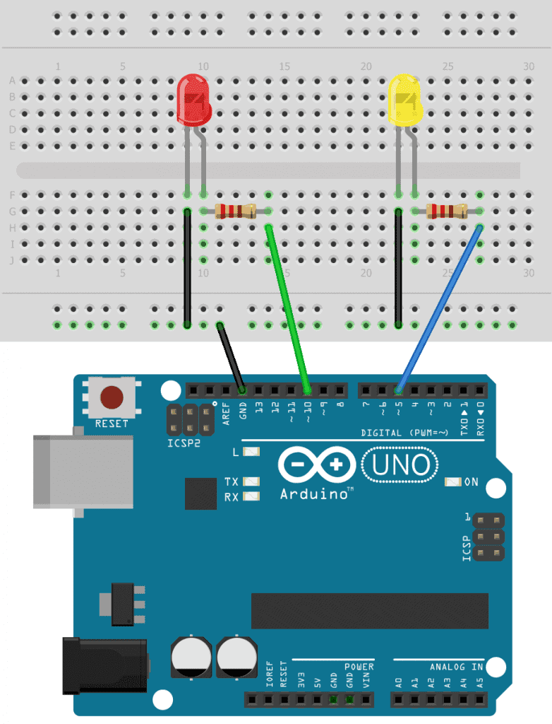
Using Timer Interrupts to Blink Two LEDs
To demonstrate how to use timer interrupts, let’s build a project that has two blinking LEDs. A yellow LED will blink at a rate of 500 milliseconds, and a red LED will blink at a rate of 5 seconds.
The typical method to blink LEDs uses the delay() function, but that won’t work in this case so we need to use a timer interrupt to control one of the LEDs.
Here are the parts you will need to build the project:
Connect the circuit following the diagram below:
To make the programming easier, we’re going to use a library called Timer1. Go to this link to download the library’s ZIP file and install it on your computer.
Once the Timer1 library is installed, upload this code to your Arduino:
#include <TimerOne.h>

void setup() {
  pinMode(10, OUTPUT);
  pinMode(5, OUTPUT);

  Timer1.initialize(5000000);
  Timer1.attachInterrupt(longBlink);
}

void longBlink() {
  digitalWrite(10, !digitalRead(10));
}

void loop() {
  digitalWrite(5, HIGH);
  delay(500);
  digitalWrite(5, LOW);
  delay(500);
}
Explanation of the Code
At the top of the sketch, we include the Timer1 library. The yellow LED will be blinking on and off once every 500 milliseconds. The red LED will be switched on and off every five seconds, which is a much longer time. So we’ll set up the timer interrupt to control the red LED.
In the setup() section, we set the pin modes of pin 10 and pin 5 as outputs. The Timer1 library can only use pins 9 and 10 for timer interrupts, so we will use pin 10. Pin 5 will be used in the loop() section to blink the yellow LED every 500 milliseconds.
In the setup() section, we use Timer1.initialize() to initialize the timer. The argument of the initialize() function sets the length of time before the interrupt is triggered, in microseconds. In the sketch above, the argument of the initialize() function is 5000000 microseconds, so the timer interrupt will be triggered once every five seconds. With the Timer1 library, the minimum interrupt period is 1 microsecond and the maximum interrupt period is 8,388,480 microseconds.
Next, we attach the interrupt service routine with Timer1.attachInterrupt(). The attachInterrupt() function only takes one argument – the name of the interrupt service routine. In the sketch above, the ISR is called longBlink(). So every time the timer reaches five seconds, the longBlink() ISR will be executed.
The code for the longBlink() ISR has a digitalWrite() function that toggles the red LED on and off. Normally we would use the delay() function to blink an LED on and off. But only one interrupt service routine can run at once, and since the delay() function itself uses an ISR, it can’t be used inside another ISR.
So we need a different way to turn on and off pin 10. Instead of using the delay() function, we can take a digital read of pin 10 and use that as the value to write. So we use !digitalRead(10) as the second parameter of the digitalWrite() function. The exclamation point is the boolean operator for NOT. This will digital read the current state of pin 10, then digital write pin 10 with the opposite value. If pin 10 is high it will be written low, and if pin 10 is low it will be written high. This is a pretty useful way to toggle an LED and it only uses one line of code.
In the loop() section, we have the code that blinks the yellow LED. This is how we normally blink an LED with the delay() function to pause between digital writes.
If everything is working correctly, the yellow LED should blink once every 500 milliseconds and the red LED should blink on for five seconds and off for five seconds. This is a really simple example, but timer interrupts are useful in a lot of other ways too. Instead of using the ISR to turn on an LED, you could use it to read a sensor at a timed interval. Or you could use it to trigger a 5 volt relay while continuously reading a sensor.
Hope this has helped you to use hardware interrupts and timer interrupts on the Arduino. Feel free to leave a comment below if you have any questions!

Is there any particular reason you didn’t mention that you changed where the button was wired when you inserted the ISR? Yes, it’s obvious, if you’re looking for it, in the video when you’re pressing the button, but if you’re not looking for it, you press the button and nothing happens. Might be something you’d want to mention?