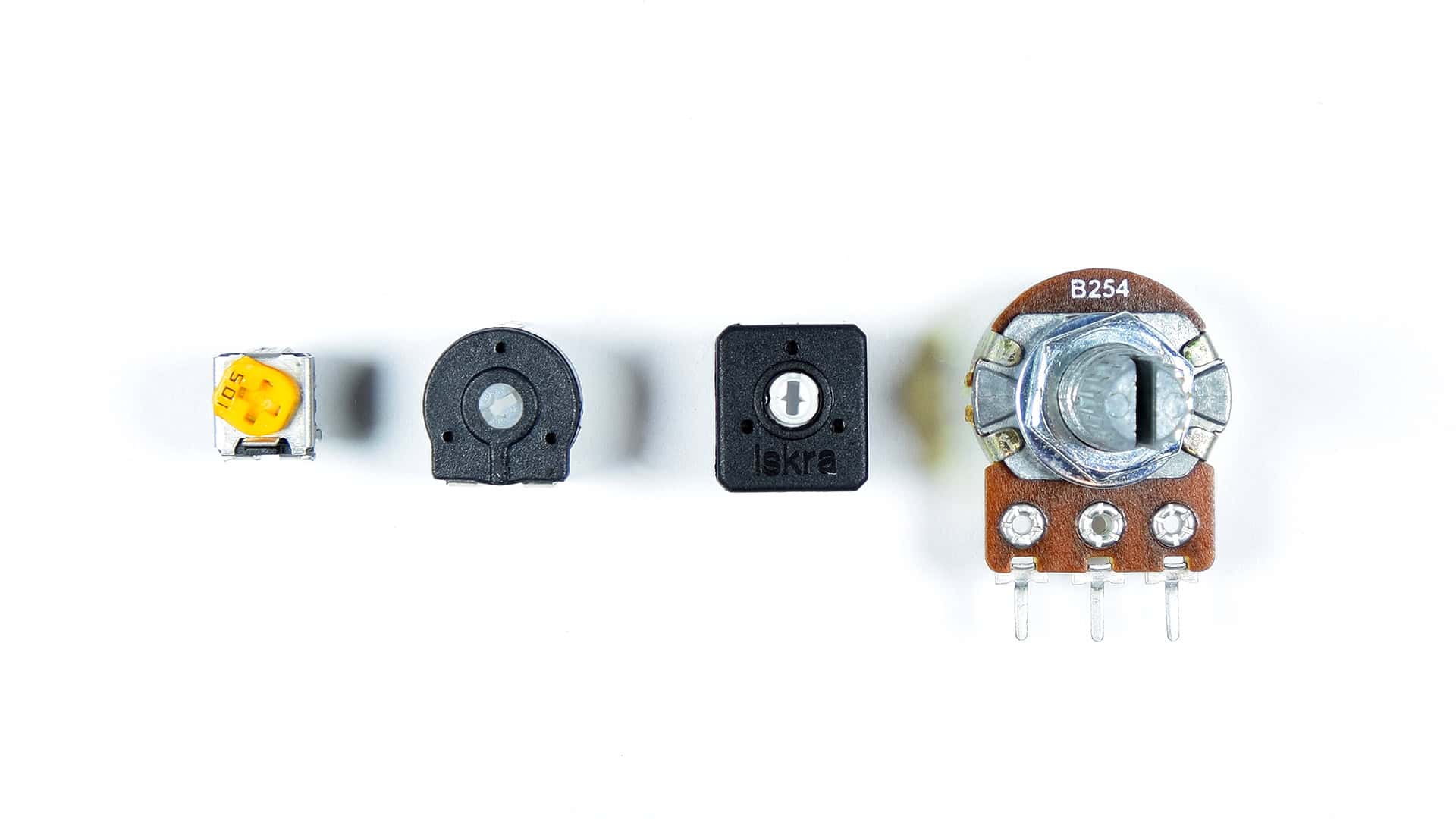
Potentiometers are a type of variable resistor. Some variable resistors, like thermistors, change resistance when the temperature changes. Other variable resistors, like photoresistors, change their resistance with changes in light. Potentiometers change their resistance when you turn a dial.

Potentiometers are everywhere in electronics projects, because they’re an easy way to adjust the resistance and voltage in a circuit. They can be used to adjust the volume of an amplifier, control motors, or adjust the contrast of an LCD display.
In this article, we’re going to learn how potentiometers work and how to use them with an Arduino. We will also see how to read analog voltages, and how to use the serial monitor. Lots of Arduino sensors output an analog voltage just like a potentiometer. The same concepts used to setup and program a potentiometer can be used to setup a wide variety of other sensors and devices on the Arduino.
Watch the video for this tutorial here:
How Potentiometers Work
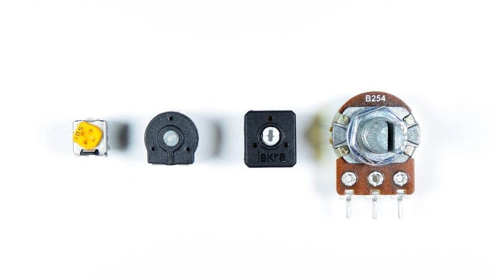
Potentiometers come in a variety of shapes, sizes, and resistance values. But they all pretty much do the same thing, and that’s change resistance when you turn the dial. Most potentiometers have three pins – a center pin, and two outer pins:
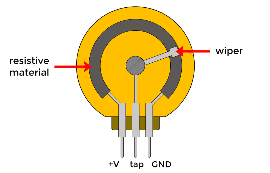
The two outer pins are connected by a piece of resistive material that forms a semi-circle inside the body of the potentiometer. The center pin is connected to a wiper that rotates when you turn the knob. The wiper slides along the resistive material, so depending on the position of the knob, there is either more or less resistive material in the path of electrical current, so the resistance changes.
Normally you connect one of the outer pins to positive and the other pin to ground. The center pin is the “tap” that provides the varying voltage. If one outer pin is connected to 5 volts, and the other to ground, the center pin will vary between 0 and 5 volts as you turn the knob. This is a type of voltage divider.
Voltage Dividers
Voltage dividers are used to step down, or reduce the voltage in a circuit. A voltage divider consists of two resistors in series. One resistor is connected to a voltage source, and the other resistor is connected to ground. Voltage dividers have an input voltage and an output voltage.
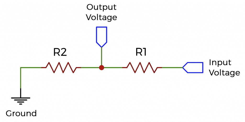
If you use the Arduino’s 5 volt pin to supply the voltage, the input voltage will be 5 volts. The output voltage is taken from a wire connected between the two resistors. It will be between 0 and 5 volts, depending on the resistance of the two resistors. If R1 and R2 have the same resistance, the output voltage will be exactly half of the input voltage, or 2.5 volts. If R2 has a very high resistance, the output voltage will be close to 5 volts. If R1 has a very high resistance, the output voltage will be close to zero.
Potentiometers
Potentiometers work the same way that voltage dividers do, except in a potentiometer, the resistances of R1 and R2 change when you turn the dial. This creates a variable output voltage that you can set to any value between the input voltage and zero volts.
Here is the schematic symbol of a potentiometer:

The arrow pointing to the resistor represents the wiper on the center pin. The ends of the resistors represent the two outer pins.
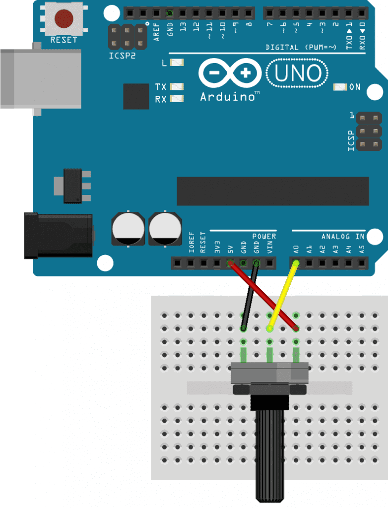
How to Connect a Potentiometer to the Arduino
Let’s use the Arduino to read the output voltage from a potentiometer.
These are the parts you will need:
Connect a potentiometer to the Arduino like this:
Output Raw Potentiometer Values to the Serial Monitor
Once the potentiometer is connected, upload this sketch to your Arduino:
void setup() {
  Serial.begin(9600);
}

void loop() {
  int rawValue = analogRead(A0);

  Serial.println(rawValue);

  delay(100);
}
This sketch will display the raw potentiometer values on the Arduino’s serial monitor. In the loop section, we set the rawValue variable equal to the analogRead() function. The analogRead() function only needs one argument – the analog pin number you want to read the voltage at. We want to read the voltage at the center pin of the potentiometer, which is connected to analog pin A0, so we put A0 as the argument.
The analogRead() function returns the ADC value of the analog pin it’s measuring. The ADC converts the analog voltage measurement to a number between 0 and 1023. A 0 voltage has an ADC value of zero, and a 5 volt reading has an ADC value of 1023. Voltages between 0 and 5 volts are mapped to values between 0 and 1023.
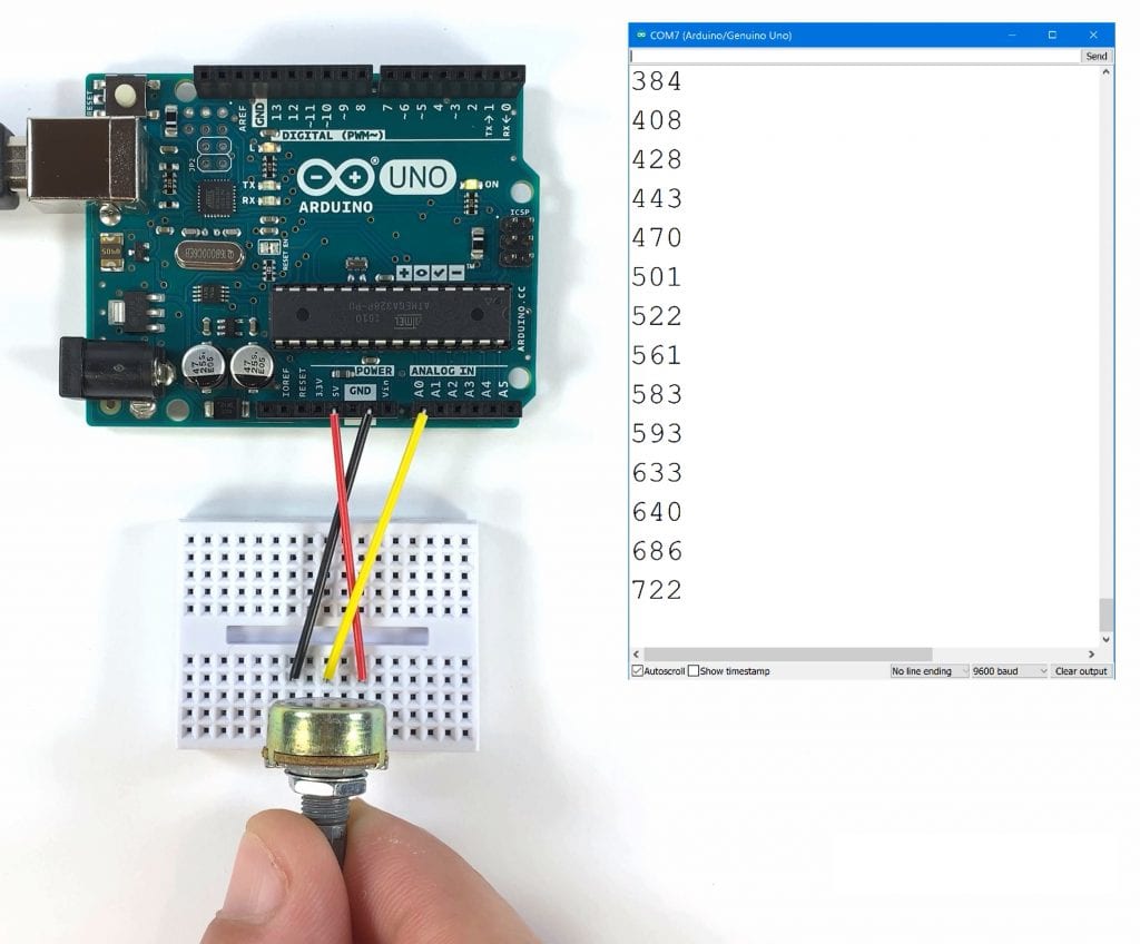
Turning the potentiometer all the way to the left should drop the value to zero. Turning it all the way to the right should increase it up to 1023. This is nice, but it would be better if we could print the actual voltage instead of the raw ADC values. To do that, we’re going to need to convert the raw values into voltage using some simple math.
Output Potentiometer Voltage to the Serial Monitor
This sketch will display the voltage output by the potentiometer on the serial monitor.
void setup() {
  Serial.begin(9600);
}

void loop() {
  int rawValue = analogRead(A0);

  float voltage = rawValue * (5.0 / 1023.0);

  Serial.print(voltage);
  Serial.println(" Volts");

  delay(100);
}
The rawValue variable already has the ADC readings from analog pin A0. We just need to convert those readings to voltage. To do that, we create another variable called voltage, which will store the results of our voltage calculation. The voltage variable is declared as a float since the voltage readings will have a decimal point. The range of voltage we will be measuring is 0V to 5V, and the range of the ADC values is 0 to 1023. To convert the ADC values to voltage, we need to multiply rawValue by 5, then divide by 1023.
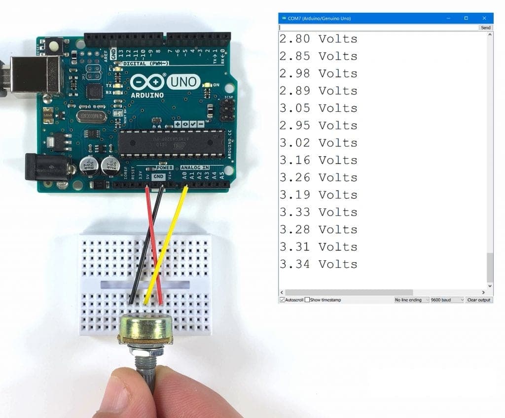
So now you can see the output from the potentiometer in volts instead of raw ADC values. This will let you really see what’s happening to the potentiometer’s output voltage when you turn the dial. The code for reading a potentiometer is the same code you would use to read any sensor that outputs an analog voltage. First you get the raw ADC value with analogRead(), then you do some math to convert the raw ADC value to the units you want. Next you just print it to the serial monitor, or use it in a function to make the Arduino do different things depending on the reading from the sensor.
Thanks for reading and be sure to leave a comment if you have a question about anything…


Thanks for your interesting and well explained articles Scott