Before we jump into a deeper discussion on prototyping boards, let us first recall what a prototype is. A prototype is a sample or model of a product or device built to test a concept or idea. The term prototype is used in a variety of contexts. For this tutorial, we are going to use it in the context of electronics. Creating a prototype is an essential step to test and evaluate your innovation ideas.

What is Prototyping?
In electronics, prototyping means building an actual circuit to a theoretical design to verify that it works. An electronics designer often builds the first prototype from breadboard or stripboard or perfboard and usually uses them to test circuits. They are generally called prototyping boards.
Prototyping boards have holes to which you affix electronic components to build your desired circuit. These components can be attached with or without solder depending on the type of board. It is always recommended to test your circuit diagram first. There are many electronics prototyping boards available in the market. The two prototyping boards that we are going to discuss in this tutorial are the perfboards and breadboards.
Perfboards
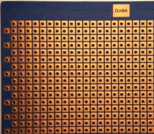
A perfboard is a prototyping board that is a thin sheet with holes at standard intervals across a square-shaped grid with a spacing of usually 0.1 inches. Square cover pads cover these holes. Inexpensive perfboards may have pads on only one side of the board, while better quality perfboards have pads on both sides. When using a perfboard, you make all connections using either wire wrap or miniature point to point wiring techniques. Other boards usually need to use the solder for attaching components.
The absence of default connectivity on perfboard gives the designer more freedom in positioning components. Circuits assembled on perfboard are not necessarily fragile but maybe less impact-resistant than printed circuit boards.
How to Use a Perfboard
First of all, you must have a plan for your circuit. Then, make a clear schematic diagram of the circuit you are planning to place on the perfboard. Have clear and understandable connections and locations of the components before building the circuit on the perfboard. Keep in mind the spacing of your perfboard while designing your layout.
Afterward, you can solder the components on their places and make the required electrical connections. Avoid excessive use of wires, if possible. Minimal use of wires will make the circuit clearer, more presentable and understandable.
Breadboards
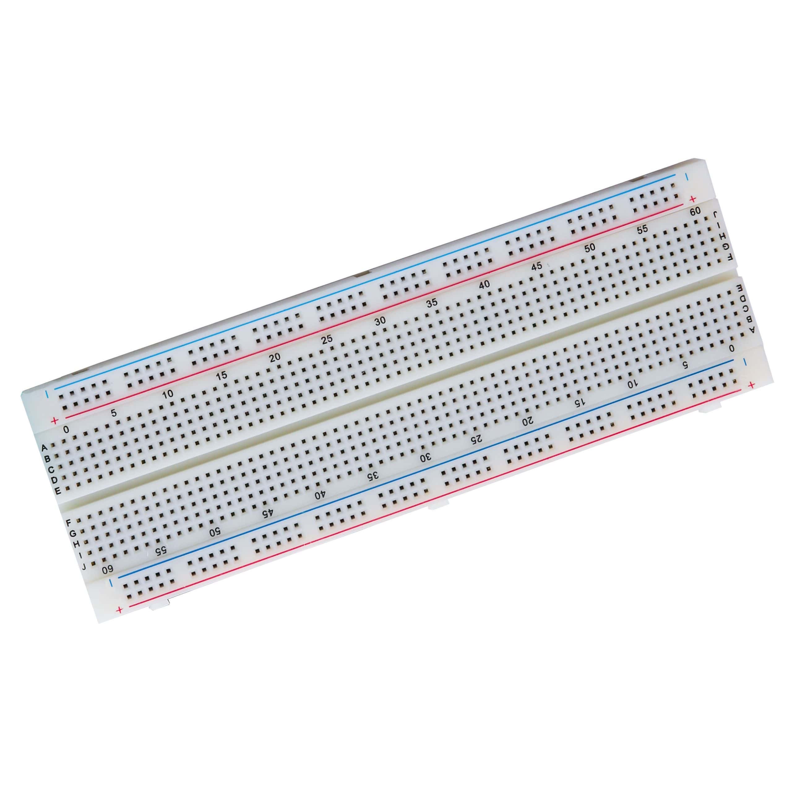
The most popular prototyping board is the breadboard. It serves as a construction base for testing if a circuit works. Just like any other prototyping board, it consists of holes where you affix your electronic components. A modern solderless breadboard socket consists of a perforated block of plastic with numerous tin-plated phosphor bronze or nickel silver alloy spring clips under the perforations. The spacing between the clips is typically 0.1 inches.
As they are mostly developed from white or dirty white plastics, this board doesn’t need solder for attaching components. And because it does not need soldering, it is reusable which makes it easy to use for creating temporary prototypes and popular among students. You can use it for a variety of projects varying from simple to high level digital or analog circuits.
Different Sizes of Breadboards
Breadboards come in different sizes:
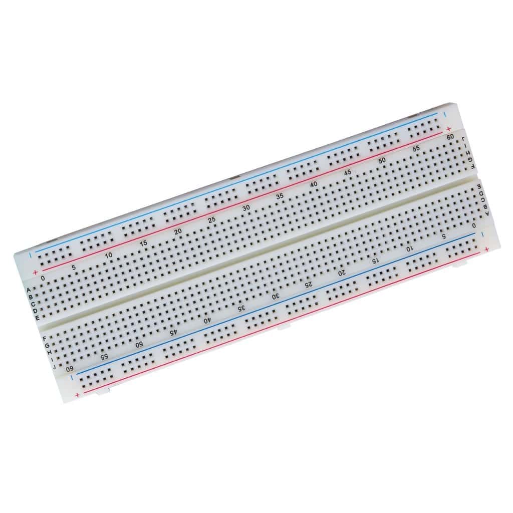
- A full size breadboard typically consists of around 56 to 65 rows of connectors, together with power rails on each side:
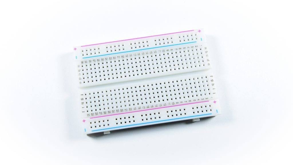
- A half-size breadboard is half the size of a full-sized breadboard:
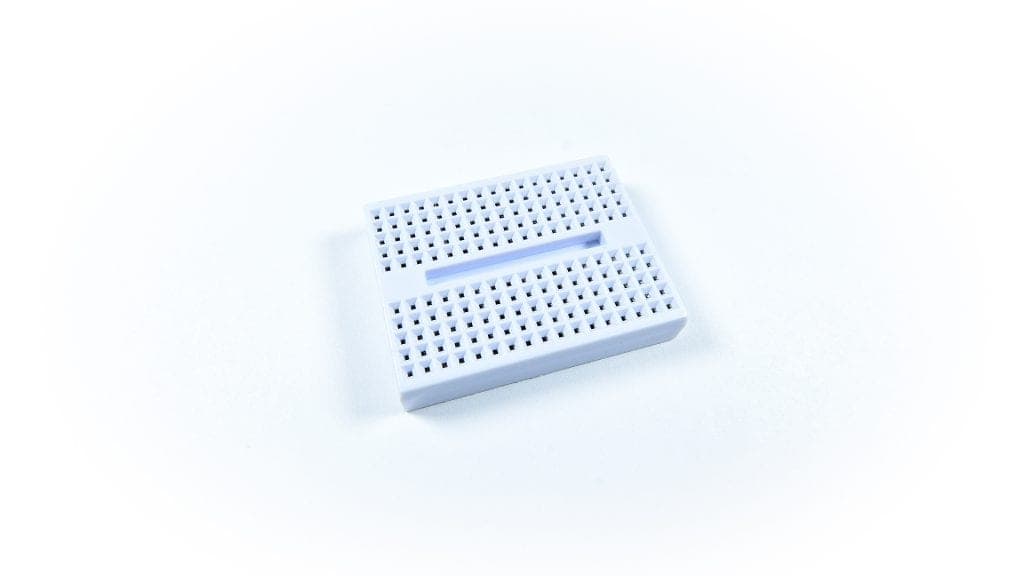
- A mini breadboard is even smaller:
How to Use a Breadboard
Just like using a perfboard, we start with preparing the schematic diagram and components of the circuit that you want to put on the breadboard. For prototyping purposes, you can easily place your electronic components into the holes of the breadboard. There is no need to use any specific tool in a solderless breadboard.
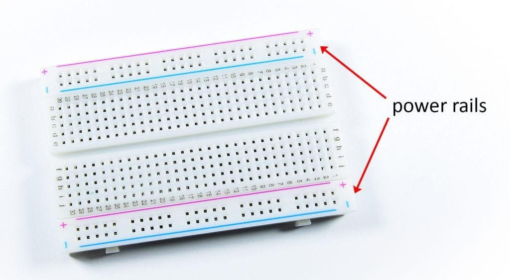
Some breadboards have labels over them to make it easier to use. Keep in mind that every row of five holes (A-E or F-J) are electronically connected. There are no electric connections present between the row H of any half-row and the holes of the other half-row. For the two hole strips running in between “+” and “-“, an electrical connection is present throughout each whole column strip. These columns are used for providing power and ground connections.
These vertical strips for power and ground connections are called power rails. These power rails are metal strips that are identical to the ones that run horizontally. These power rails give you lots of easy access to power, labeled as “+” and “-” to indicate positive and negative. The power rails on either side of the breadboard are not connected. A jumper wire can be used to connect each side.
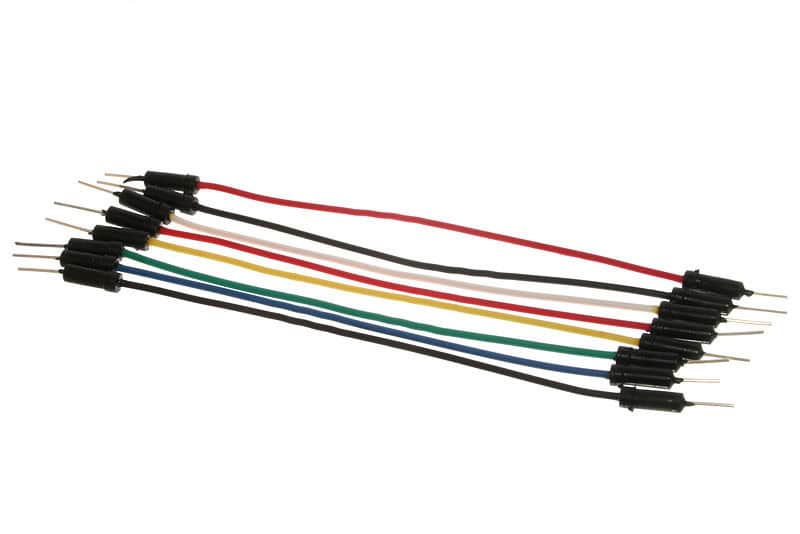
Jumper Wires
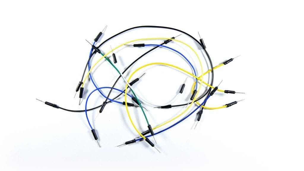
Jumper wires are extremely handy when you’re prototyping with solderless breadboards. These are available in the market at cheap prices, but you can make your own too. Jumper wires are simply wires that have connector pins at each end. This allows them to be used to connect two points to each other without soldering. Jumper wires come in different lengths and a variety of colors. But these colors don’t actually mean anything. However, colors can be used for legends to easily identify the connections. So, it is better to make use of the colors!
Different Types of Jumper Wires
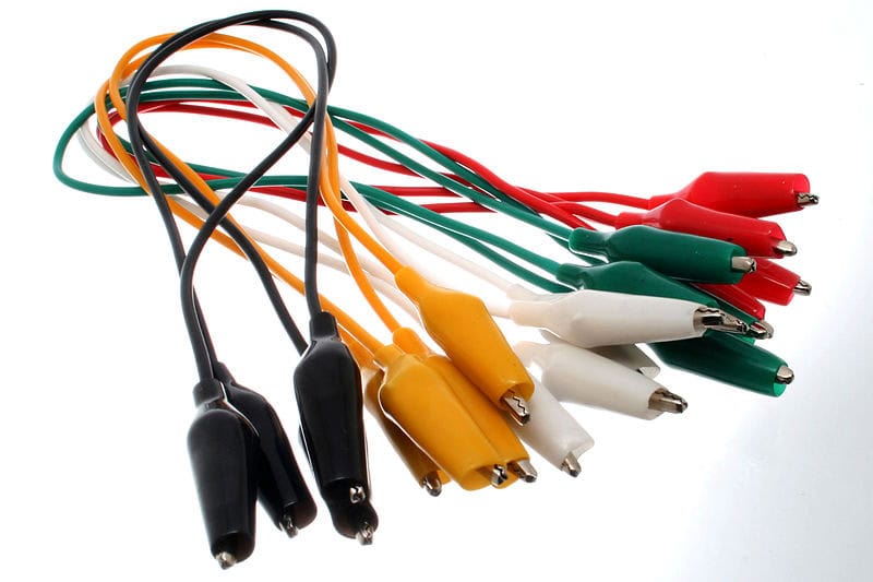
Jumper wires have three versions: male-to-male, female-to-female, and male-to-female. The most typically used is the male-to-male, because its ends have pins that can plug into the holes of the breadboard and on female ends of another jumper wire. As mentioned, the female ends are where you plug into. They are like the holes in the breadboard.
Another version of jumper wires is the alligator clip. They consist of two spring metal clips connected by wire. They can be clipped instead of insertion. You can also use an alligator clip as a connection to a male-to-male jumper wire.
Feel free to leave a comment below if you have any questions, or would like to add some of your favorite prototyping tips and tricks!