
The Arduino can only output two voltages – 0 volts and 5 volts. But many devices like LEDs, servos, and motors need to be powered by a range of voltages between 0 volts and 5 volts. Luckily, the Arduino is capable of pulse width modulation, which can be used to simulate any voltage between 0 volts and 5 volts.

In this article, we will learn how pulse width modulation works and how to generate pulse width modulation signals with an Arduino Uno.
Watch the video for this tutorial here:
Pulse Width Modulation
A pulse width modulation signal is made up of short, high frequency pulses of current. The signal looks like a square wave, with the voltage switching from 5 volts to 0 volts very quickly:
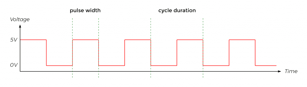
On the Arduino, the pulse width modulation frequency is around 500 Hz, so there are 500 of these cycles happening every second. The duration of each cycle is only about 2 milliseconds.
The duration of the high part of the signal is called the pulse width. The duration of the high and low parts of the signal is called the cycle duration. The percentage of the pulse width duration to the cycle duration is called the duty cycle:

By changing the duty cycle, we can change the apparent voltage to any value between 0 and 5 volts:
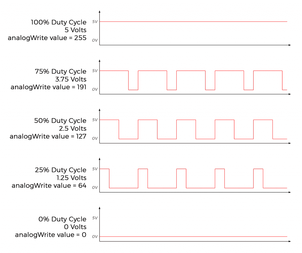
For example, with a duty cycle of 50%, the pulse width is 50% of the cycle, so the apparent voltage is 50% of 5 volts, or 2.5 volts. This corresponds to an analogWrite value of 127.
Pulse width modulation signals can only be generated from Arduino pins that have a “~” next to them:

Use analogWrite() to Generate Pulse Width Modulation Signals
The analogWrite() function can generate a pulse width modulation signal. It takes two arguments, pin and value:
analogWrite(pin, value);The pin argument is the pin number where the pulse width modulation signal will be generated. The value argument is the analogWrite value that corresponds to the duty cycle of the pulse width modulation signal. To find the analogWrite value that will produce a pulse width modulation signal with a specific apparent voltage, use this formula:

Example Project
Let’s build an example project that uses pulse width modulation to increase and decrease the brightness of an LED automatically.
These are the parts you’ll need to build the project:
Follow this diagram to connect the LED and current limiting resistor to the Arduino:
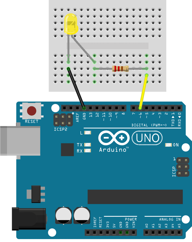
The current limiting resistor can have any value from 220 Ohms to 1K Ohms.
Programming the Arduino for Pulse Width Modulation
This program will make the LED increase to 100% brightness then decrease to 0% brightness, in an infinite loop.
Once the circuit is connected, upload this code to the Arduino:
int ledPin = 6;
int brightness = 0;
int fadeAmount = 5;

void setup() {
  pinMode(ledPin, OUTPUT);
}

void loop() {
  analogWrite(ledPin, brightness);

  brightness = brightness + fadeAmount;

  if (brightness <= 0 || brightness >= 255) {
    fadeAmount = -fadeAmount;
  }

  delay(30);
}
Explanation of the Code
At the top of the sketch, we declare an int variable called ledPin to store the pin number connected to the LED. Then we declare an int variable called brightness, which will store the analogWrite values as they cycle between 0 and 255. We also declare a variable called fadeAmount, which will be used to control how quickly the LED fades on and off.
In the setup() section, we use the pinMode() function to set the ledPin as an output.
In the loop() section, we have an analogWrite() function to generate the pulse width modulation signal. The first argument is the pin number that will generate the pulse width modulation signal, so we use the ledPin variable as the first argument. The second argument is the analogWrite value that sets the duty cycle. We declared a variable called brightness to store that value, so it’s used as the second argument.
The next line is brightness = brightness + fadeAmount;. This takes the brightness variable and adds the fadeAmount variable to it each time through the loop. We declared fadeAmount equal to 5, so this will make the brightness variable increase by 5 with each cycle of the loop.
Then we have an if statement with a condition that says “if brightness is less than or equal to 0, or brightness is greater than or equal to 255″, execute the code in the body. In the body of the if statement we have fadeAmount = -fadeAmount;.
How the Program Works
At the beginning of the program, brightness is set equal to 0:
int brightness = 0;In the first cycle through the loop() section, brightness equals 0, so a pulse width modulation signal with a duty cycle of 0% will be sent to the ledPin (pin 6) and the LED will be completely off:
analogWrite(ledPin, brightness);On the next line, the fadeAmount variable is added to the brightness variable. We declared fadeAmount equal to 5 at the top of the sketch, so brightness will now equal 5:
brightness = brightness + fadeAmount;Now the condition of the if statement asks “is brightness less than or equal to 0, or greater than or equal to 255?”:
if (brightness <= 0 || brightness >= 255) {
  fadeAmount = -fadeAmount;
}
No it’s not, brightness is equal to 5. So the code inside the if statement is skipped, and the program jumps to the first line after the if statement, which is a delay of 30 milliseconds:
delay(30);Now the program returns to the top of the loop() section. The brightness variable now equals 5, so the analogWrite() function writes an analogWrite value of 5 to the LED.
On the next line, fadeAmount is added to brightness again, so brightness equals 10. The if statement checks if 10 is less than or equal to 0, or greater than or equal to 255. It’s not, so the code inside the if statement is skipped again. The program keeps looping over and over, adding 5 to the brightness value with each iteration of the loop() section.
But the brightness value will quickly reach 255 and the LED will be at full brightness. At that point, the Arduino reaches the if statement and finds that yes, 255 is greater than or equal to 255, so it enters the body of the if statement:
fadeAmount = -fadeAmount;This changes the value stored in fadeAmount from 5 to -5.
In the next cycle through the loop, when the program reaches brightness = brightness + fadeAmount, 5 will be subtracted from brightness since fadeAmount now equals -5. This decreases brightness from 255 to 250. The program keeps looping, subtracting 5 from brightness with every iteration of the loop until brightness reaches 0.
When brightness equals 0, the condition of the if statement will be true, so the program enters the body of the if statement. Since fadeAmount still equals -5, the expression will look like this:
fadeAmount = -(-5);The negative of -5 equals positive 5, so fadeAmount will equal positive 5. Now 5 will be added to the brightness variable each time through the loop. This makes the value stored in brightness cycle up and down from 0 to 255, making the LED increase and decrease in brightness in an infinite loop.
Set this up on your own and see how the LED’s brightness changes by using different values for the fadeAmount variable. You can also change the range of the LED’s brightness by changing the values in the condition of the if statement.
Feel free to leave a comment below if you have any questions!


How are the Schmitt Trigger and capacitor used?
Ralph
Could I limit the maximum analogWrite to correspond with the LED’s rated voltage and omit the resistor?
If you want to use PWM for analog voltage output, for example a VU meter or a LM3914 with LED bar, add an RC bridge (3k3+10uF). A fast chip can see the output as a blockwave, not a ‘linear voltage’