A linear power supply is a power supply unit (PSU) that does not contain any switching or digital components. It has some outstanding characteristics compared to switching PSUs such as very low noise and ripple, immunity from mains-borne noise, simplicity, robustness, ease of design, and repair. They can also generate very high voltages (thousands of volts) and very low voltages (less than 1V). They can easily generate multiple output voltages. On the flip side, they are large in size and heavy, and are needing more heat-sinking. Linear power supplies have been around for several decades, long before the advent of semiconductors.

Linear PSU’s can be fixed, for example, as a 5-V supply that you might need for a logic circuit, or several fixed supplies needed for a PC (+5, +12, or -12V). On a bench lab-type PSU, you would want to use a variable PSU. In addition to single supplies, you can also get dual supplies, say for op-amp circuits ±15V and even dual tracking supplies that are voltage-locked to each other in supplies where drift is not negligible.
Some examples:
- +5V logic and microprocessor circuits
- +12V LED lighting, general electronics
- ±15V op amp circuits
- 0-30V bench test supply
- +14.5V battery charger
In this article, we will look at the individual components of a PSU, then design a small 12V supply from scratch, and an adjustable dual 1-30V supply.
Deconstructing a Linear PSU
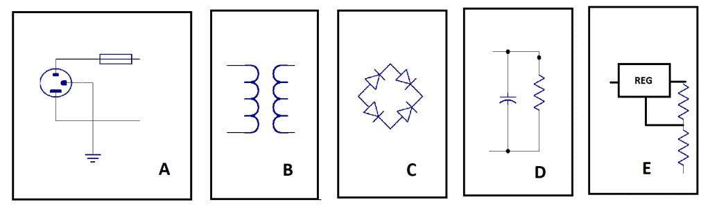
- The mains input section contains the connections to the mains, usually a switch, a fuse, and a pilot lamp of sort. Use good grounding, and insulate any mains parts in the internal wiring with sleeving to protect accidental contact.
- The transformer is chosen according to the required output voltage and effectively isolates all other circuits from being mains referenced. The transformer may have multiple primary taps to allow for different mains input voltages and multiple secondary taps appropriate for the output voltage required. In addition, there is a copper foil shield between the primary and secondary taps to help reduce capacitive coupling to high-frequency mains noise.
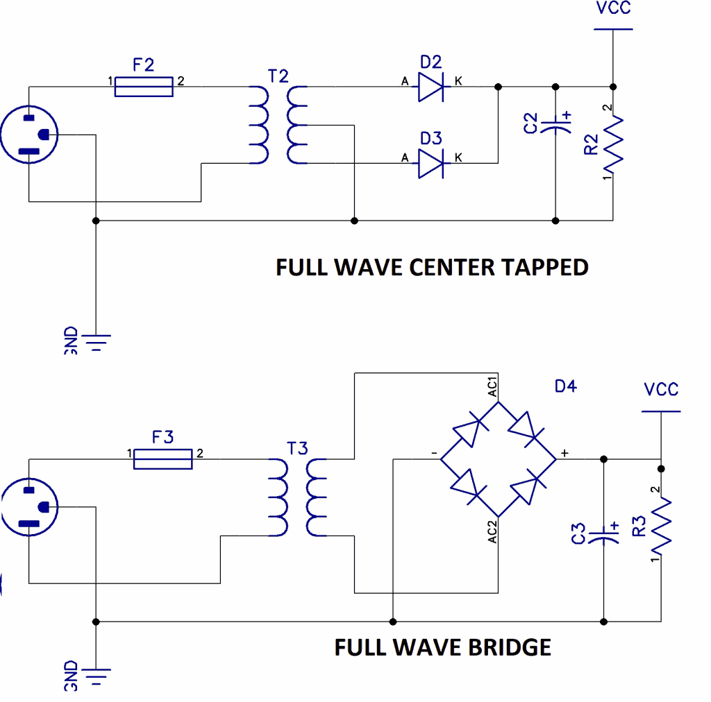
- The rectifier can be as simple as a one-series diode (unsuitable), a full-wave center-tapped bridge, or a full-wave bridge. Diodes (rectifiers) used should be specified. They are cheap and small and use heftier ones than designed. In my experience repairing many faulty PSU’s, problems are usually caused by diode failure either from too much current or mains over-voltage spikes. Given this, select a diode with a high PIV (peak inverse voltage). When you mount diodes, keep the leads on the long side as this is where most of their heat is being dissipated. In high-voltage supplies, it is common to see small capacitors in parallel with the diodes to help them recover faster.
- The capacitor is a very hard-working component and has to charge up to the peak of the secondary voltage (Vsec * 1.414) and then rapidly discharge into the load. Aluminum foil capacitors are basically a roll of toilet paper and aluminum filled with oil, and they have a reputation for drying out and consequently losing capacitance. If possible, place them well away from any heat sources in your layout. Tantalum capacitors have a much lower ESR (equivalent series resistance), thus handles ripple better. You can use them in the regulator circuit. When wiring up, try to bring all the grounds to a single point. The capacitor is a good point to use. The figure below represents a resistor, which is excellent engineering to bleed this cap when the PSU is turned off. The regulator also needs to have a small output current when not on load; a 1k would suffice.
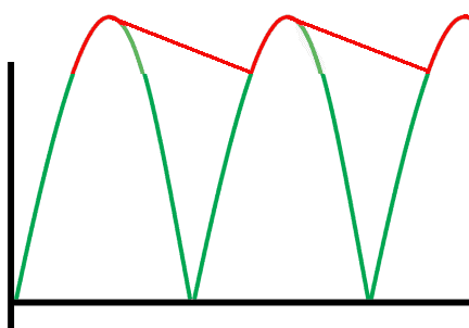
In the figure below, the green curve is what the waveform would look like without a capacitor, and the red waveform is the “topping up” of the cap on each half cycle and then the discharge due to the load current. The resulting waveform is the ripple voltage.
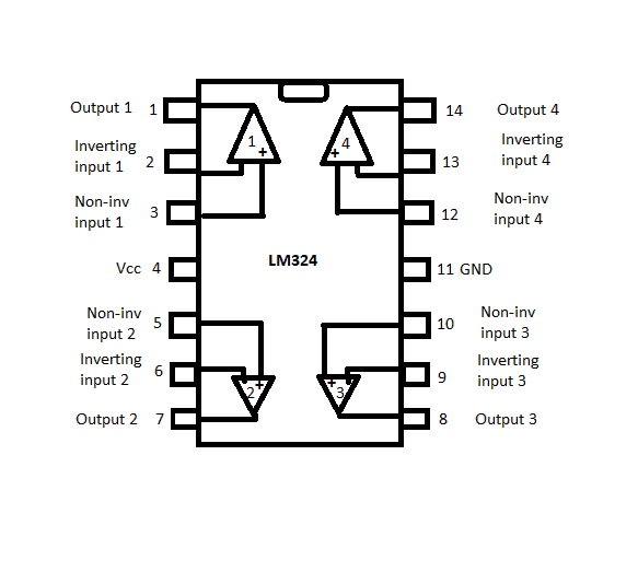
- The regulator comes in many types: series, shunt, simple and complex. There will be a dedicated article on regulators, but for this tutorial, we will focus on designing two simple IC-based regulators with a 7812 fixed regulator and an LM317 adjustable regulator.
Designing a Linear Power Supply
When designing a PSU, you start at the end and work your way back to the beginning. The key specification is the voltage we want at the output and how much current we can draw out of it without dropping the voltage. For this project, let’s aim for 12V at 1A and 3V dropout over the regulator. Any regulator is going to have a certain required difference between the input and output voltages to work properly. If not specified, assume this to be at 3V minimum. Some of the regulators we use here will be only 2V.
If we need 12V at the output, then we need 12+3 = 15V at the capacitor. Now, as this capacitor charges and discharges, there should be an AC component present, and this is the ripple voltage (Vripple). The larger the current being drawn off the capacitor, the worse the ripple, and we need to specify this as well. Opting for 10% ie, 1.2 Vpp, the cap is calculated as follows:
where f is 50 or 60 depending on your mains frequency. Hence, we need:
This leads us back to the diodes. Because the diodes are not only supplying the load current but also the capacitor charge current, they will be using more current.
In the full-wave bridge, the current is 1.8 * Iload. In the center-tapped, it is 1.2 * Iload. Given these, we should be using at least 2A diodes.
This now leads us back to the secondary of the transformer, and its specific voltage. In any robust system, we must look at tolerances. If we are to follow just the minimum design requirement, the regulator input could fall below dropout largely affecting the mains. Commercial designs usually specify ±10%, so if our supply is 230V, that means it could drop to 207V.
Thus, the voltage needed on the secondary is as follows:

where 0.92 is transformer efficiency and 0.707 is 1/√2
Vreg is the regulator dropout, Vrect is the drop across 2 diodes and is 2*0.7 for the center tap circuit and 4*0.7 for the full bridge. Vripple was specified as 10% of 12V, or 1.2V, so
Vsec = 15.03V
This means an off-the-shelf 15V transformer should suffice. Sometimes you can’t get a good match for the transformer and need to select another with higher voltage. The down side of this is that the regulator is going to have a higher voltage across it, and as a result, more power to dissipate in its heat sink.
The last thing to specify now is the transformer size in VA. It is an easy and common mistake to think that VA would be Vsec*Iload ie 15*1 = 15VA. But we must not forget that the transformer is also charging the capacitor so depending on the configuration, 1.2 or 1.8 * Iload means a big difference, ie, 1.8*1*15 = 27VA.
That, now, concludes the design. But what about the fuse? That is a whole science on its own, but for this simple PSU, I would rate it at 2 times the primary input current. So in this case, VA is 27 and mains Vin is 230V and I = 2*27/230 = 250mA.
Now we can add the last few components to the regulator:
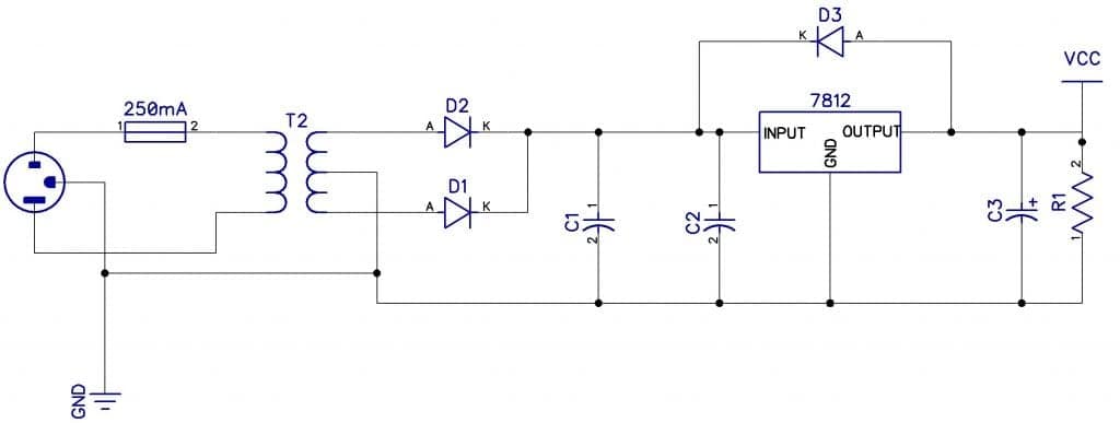
For C1, we designed it to be 4200uF. But because the regulator will remove much of the ripple, it could be less, or half of that which is 2200uF. The purpose of C2 and C3 is to provide stability and noise immunity to the regulator. National Linear usually makes C2 10uF and C1 1uF. Ideally, these should be tantalum types, but if you are forced to use aluminum, you should double the value.
D3 is often neglected but important. If there is a short on the input of the regulator, any stored capacitance in the load Vcc including C3 will discharge into the backside of the regulator, and possibly killing it. But D3 bypasses that.
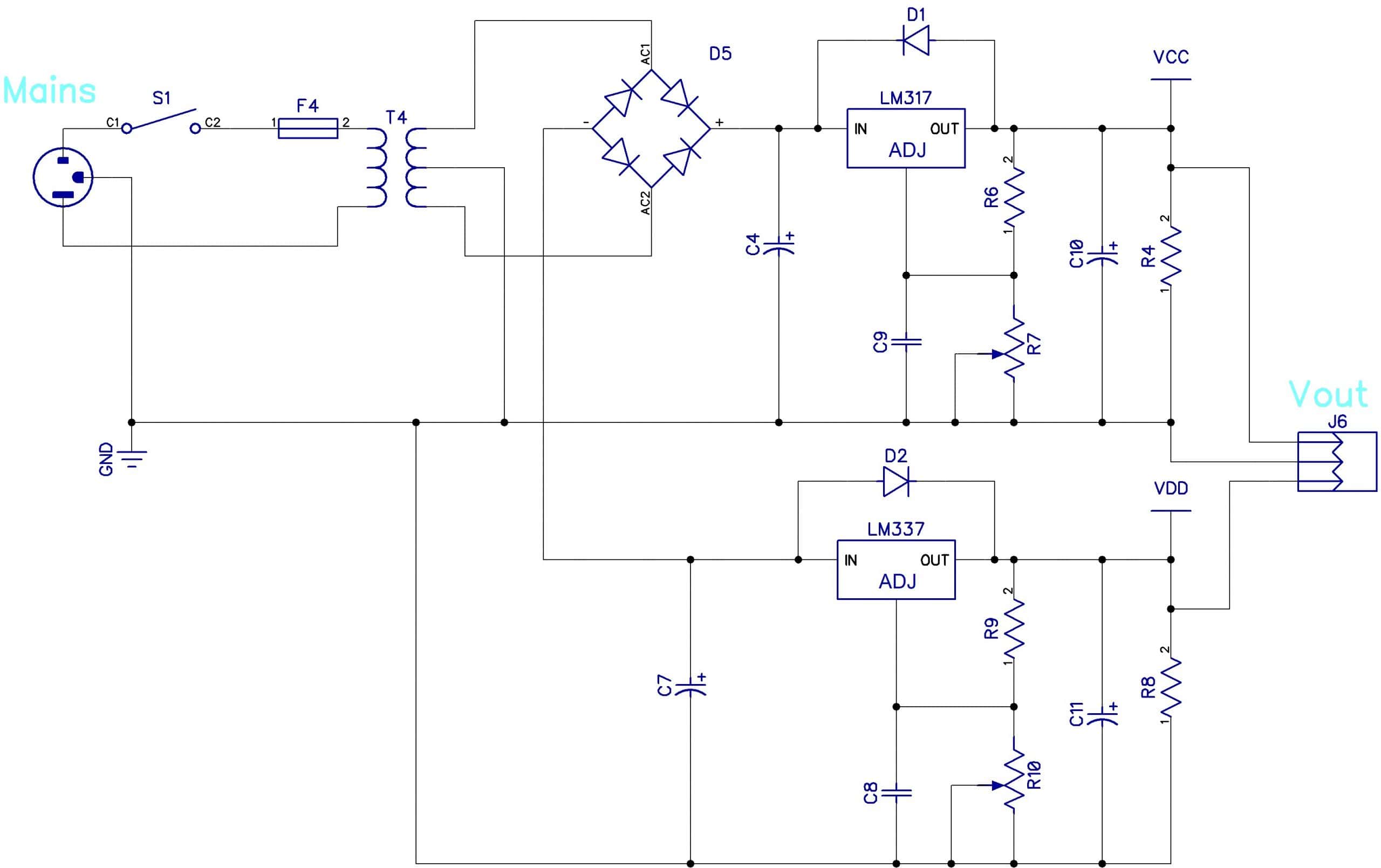
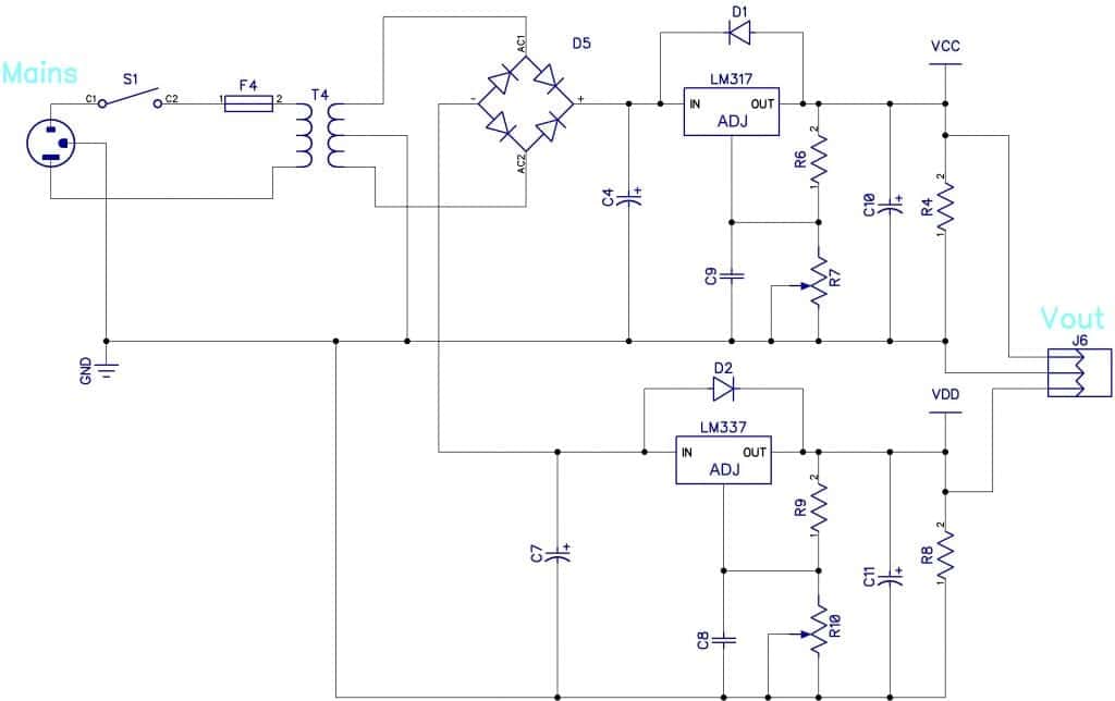
Now, let’s replace the fixed regulator with an adjustable one based on the popular and easy to use LM317 and add the complementary negative version, LM337, to form a dual adjustable PSU. Note that we have used a center-tapped transformer as well as a full bridge rectifier. The following notes apply equally to the negative half of the PSU. The only thing left to design is R6 and R7.
If you make R6 = 220, then for any voltage between Vmax and Vmin, R7 = (176* Vout) – 220. So if you wanted 9V, R7 would be 176*9 – 220 = 1k4. You could use a dual-ganged pot of about 5 to 10k (linear) to adjust both sides at the same time. A transformer with a 25/0/25 secondary would be fine. C8 and C9 give noise immunity and can be 10uF. C10 and C11 are 1uF and C4 and C7 are 1000uF. The minimum output voltage is about 1.25V.
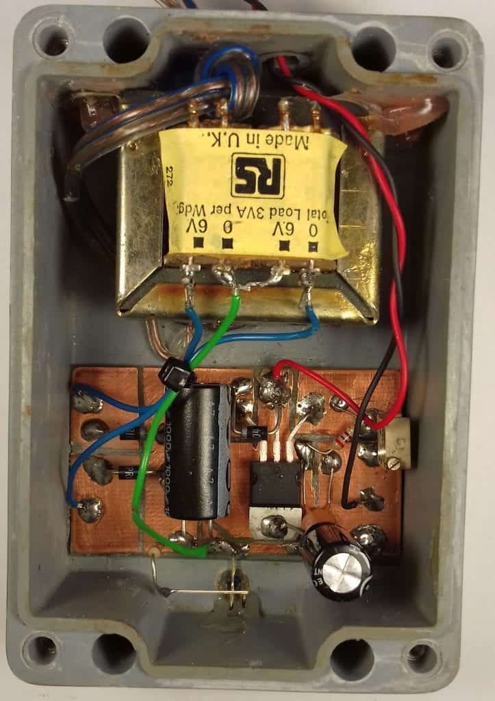
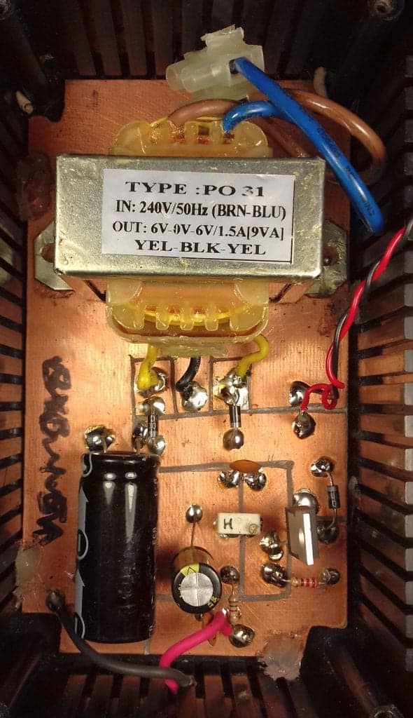
Some examples of small DIY linear PSU’s
Hope this article has answered any questions you have about linear power supplies, but leave a comment below if you need any further explanation!

In the section where the regulator is first added the capacitor values seem to be mixed up. Is C1 2200uF or 1uF? I am guessing C1 is meant to be 2200uF and C3 is meant to be 1uF. Is that right? Thanks for the great article!
Would be useful to have a list of components with values.
thx
C7 and C11 in the dual adjustable supply should be installed with the positive terminal connected to ground and the negative terminal connected to the negative voltage.
Good Job. Thanks.
I need 0- +750 VDC @ 1.5 amps regulated, 0- +600 VDC regulated @ 1 amp, 0–250 VDC @ 500mA, and 6.3 VAC & 12.6 VAC 10-15 amp supplies, all in the same device. This looks like a job for 3 transformers, a choke or two, MOSFETS, BJTs, Zener diodes, and some hefty bridge diodes, etc. I have the iron to make two 4000 VDC regulated PSUs rated for 1 Ampere each, or 2 Amps bridged. It would weigh about 600 pounds.
The voltage drop across a bridge is 2 x Vf for a full wave bridge and Vf for center tapped, not 4x and 2x as described. The reason is that for every cycle in a FW bridge, it goes thru 2 diodes so the drop is 2Vf. Also when I looked at a common rectifier 1N5401, the Vf was 1.2V, not the nominal .7.
I was able to lower the VAC of the secondary by choosing a LDO (Low dropout) regulator and Schottky rectifier diodes Vf=.3V, which you dont mention in your article. Otherwise I thank you for your areitcle,
Don’t connect DC ground directly to AC ground, because then it won’t be 100% isolated.