Comparators are devices that compare two voltages or currents and output a digital signal indicating which is larger. The output value of the comparator indicates which of the inputs is greater or lesser. A comparator compares the two inputs applied to it and produces the comparison as the output. It has two analog input terminals and one binary digital output. They are commonly used in devices that measure and digitize analog signals, such as successive-approximation ADCs and relaxation oscillators.

Use for a Comparator
Comparators are often used to check whether an input has reached a predetermined value. For example they can be used to determine when the temperature detected by a thermistor rises above a certain threshold.
Comparators consist of specialized high-gain differential amplifiers. Comparators are used to sense when an arbitrary varying input signal reaches the reference level or a defined threshold level. Such devices can be designed using various components like diodes, transistors, and op-amps. They can be found in many electronic devices to drive logic circuits.
Comparators can amplify or attenuate this input and carry out mathematical operations such as addition, subtraction, integration, and differentiation.
Inverting Comparator
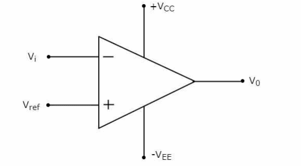
An inverting comparator is an op-amp-based comparator in which the reference voltage is applied to its non-inverting terminal, and the input voltage is applied to its inverting terminal. This comparator is called an inverting comparator because the input voltage, which has to be compared, is applied to the inverting terminal of the op-amp.
The operation of an inverting comparator is straightforward. It produces one of the two values and at the output based on the values of its input voltage and the reference voltage. The circuit diagram of an inverting comparator is shown in the following figure.
Non-Inverting Comparator
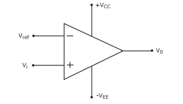
A non-inverting comparator is an op-amp-based comparator in which the reference voltage is applied to its inverting terminal. The input voltage, on the other hand, is applied to its non-inverting terminal. This op-amp-based comparator is called a non-inverting comparator because the input voltage that has to be compared is applied to the non-inverting terminal of the op-amp. The circuit diagram of a non-inverting comparator is shown in the following figure.
The LM324 Op-Amp
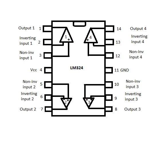
The LM324 operational amplifier IC can work as a comparator. This IC has four independent operational amplifiers on a single chip.
This is a low-power quad operational amplifier and has high stability and bandwidth designed to operate on a single power supply over a wide range of voltages. The quad amplifier can operate at supply voltages as low as 3.0 V or as high as 3.2 V with quiescent currents about one-fifth of those associated with the MC174. The common-mode input range includes the negative supply, eliminating the necessity for external biasing components in many applications. The output voltage range also includes the negative power supply voltage. The LM324 comparator circuit consists of sensor voltage, reference voltage, Vcc, ground, and output pins.
A single power source can operate an LM324 but it can also use two power supplies. The terminals or the pins used are pins 4 and 11. The power supplies will make all four op-amps operational.
For the first op-amp, the inverting input is applied at pin 2 and the non-inverting at pin 3. The output of the first op-amp is obtained at pin 1.
For the second op-amp, the inverting input is applied at pin 6, and the non-inverting at pin 5. The output of the second op-amp is obtained at pin 7.
For the third op-amp, the inverting input is applied at pin 9 and the non-inverting at pin 10. The output of the third op-amp is obtained at pin 8.
Lastly, for the fourth op-amp, the inverting input is applied at pin 13 and the non-inverting at pin 12. The output of the fourth op-amp is obtained at pin 14.
Hope this article has helped you to better understand how comparators work! Leave a comment below if you have questions about anything.


On the schematic, the two inputs of the opamp are short-circuited.
Typo spotted. The supply voltage range for LM324 is 3.0 to 32v not 3.0 to 3.2 as stated in your text