In electronics, a display driver is an integrated circuit that provides an interface between a microcontroller and a display device like an LED matrix.

A display driver typically accepts commands and data using an industry-standard general-purpose serial or parallel interface. Then, it generates signals with suitable voltage, current, timing, and demultiplexing to make the display show the desired text or image.
LED drivers control the amount of current and voltage supplied to individual light-emitting diodes (LEDs) in the display. They can also provide brightness, backlight, and color control.
Types of LED Display Drivers
LED display drivers can be broken down into the following categories:
- White light LED drivers – Good for controlling LED matrixes. They provide white light for backlighting and offers very low noise. Typical efficiencies are as high as 90%.
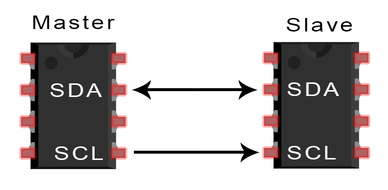
- Pulse width modulation (PWM) LED drivers – These can be programmed through an I2C compatible interface. PWM LED drivers are used for applications that require color, pattern, and intensity control.
- RGB LED drivers – Used to control the color of RGB LEDs and LED strips. All functions are controlled by software through internal registers and the SPI interface.
- Constant current LED drivers – These feature internal circuitry that monitors each LED’s loop current and automatically adjusts the generated output DC voltage to the minimum value required to produce the highest forward voltage.
- 7-segment LED display drivers – These are LED display drivers that use a combinational logic circuit that accepts a 4-bit BCD input and generates seven output signals to control seven individual display segments.
How LED Drivers Work
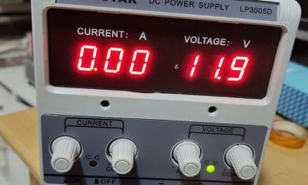
An LED driver is needed to operate and control multiple LEDs at the same time. Unlike most electronic devices, LEDs are current driven devices, not voltage driven. Even a minuscule change in voltage can lead to a huge change in current. Hence, it is important that the drive current is regulated and not the voltage. LED drivers are usually switching mode devices that convert the input voltage into a voltage at which the current drawn by the LEDs is equal to its drive current. The drive current is regulated for optimum brightness, LED service life, and battery life. A drive current lower than the maximum drive current of an LED can greatly prolong service and battery life.
An LED driver is somewhat like cruise control in a car. It helps to control the current that goes to the LED. Without the LED driver, the LEDs would become too hot and unstable, leading to thermal runaways, resulting in bad performance or failure. This means that in an LED light, the driver does all the heavy lifting. Your LED itself might be the best, but it won’t stay that way if you don’t have a good LED driver. This is because most LED lights run on low voltage with DC. Essentially, an LED driver helps to rectify the high voltage with AC from the mains power supply to low voltage with DC for the LED lights. LEDs actually work on DC power at a rather low voltage—usually between 2V to 4V.
The MAX7219 LED Display Driver
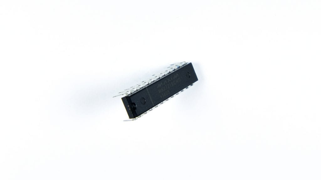
The MAX7219 8 digit display driver is a compact, serial input/output common-cathode LED display driver that can interface to a microprocessor (µP) to control 7-segment displays up to 8 digits, bar-graph displays, or 64 individual LEDs.
Uses for the MAX7219:
- Converting serial data to parallel data
- Reducing I/O pin usage of a microcontroller or processor
- Can control 64 LEDs using only three pins
- Preferred choice for controlling 7-segment displays
- Can be connected in serial to control more display segments
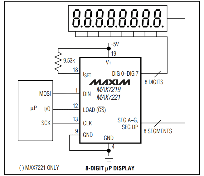
Only one external 9.53k Ohm resistor is required to set the segment current for all of the LEDs in the display.
Here is how to connect it to a 7 segment display:
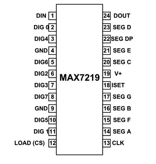
The MAX7219 comes in a 24-pin DIP package:
How to Use the MAX7219 LED Display Driver
The IC is utilized like any shift register. First, we will send serial data to the chip bit by bit, and once all data is sent, we will tell the chip to shift this serial data to the output by enabling the CS pin. Data is sent to the chip through the DIN pin. The data is sent bit by bit by setting the clock of the chip for each bit. The chip stores the serial data in its registers until all data is received. After completing data sending, we set the CS pin for the chip to shift all data stored in its register to the output. The data is output in the form of setting pins DIG0-7 and pins SEG0-7 high or low. This high and low signal is used to turn on and off individual LEDs in the display.
There are two ways to program this chip. One is to follow the instructions given in the datasheet to send the data bit by bit. The second way is to use software libraries. Depending on the microcontroller you are using, there are probably libraries available for programming the MAX7219. For example, the Arduino platform has a library called max7219. Using the libraries is the easiest way to get the required result. With libraries, you can just enter the required data to send without worrying about sending individual bits of data to the chip.
For more info about programming the MAX7219 with the Arduino, check out these articles:
Hope this helps you get started using the MAX7219 LED display driver in your own electronics projects. Let us know in the comments below if you have any questions.


