Seven segment displays are used in common household appliances like microwave ovens, washing machines, and air conditioners. They’re a simple and effective way to display numerical information like sensor readings, time, or quantities. In this tutorial, we’ll see how to set up and program single digit and multi-digit seven segment displays on an Arduino.

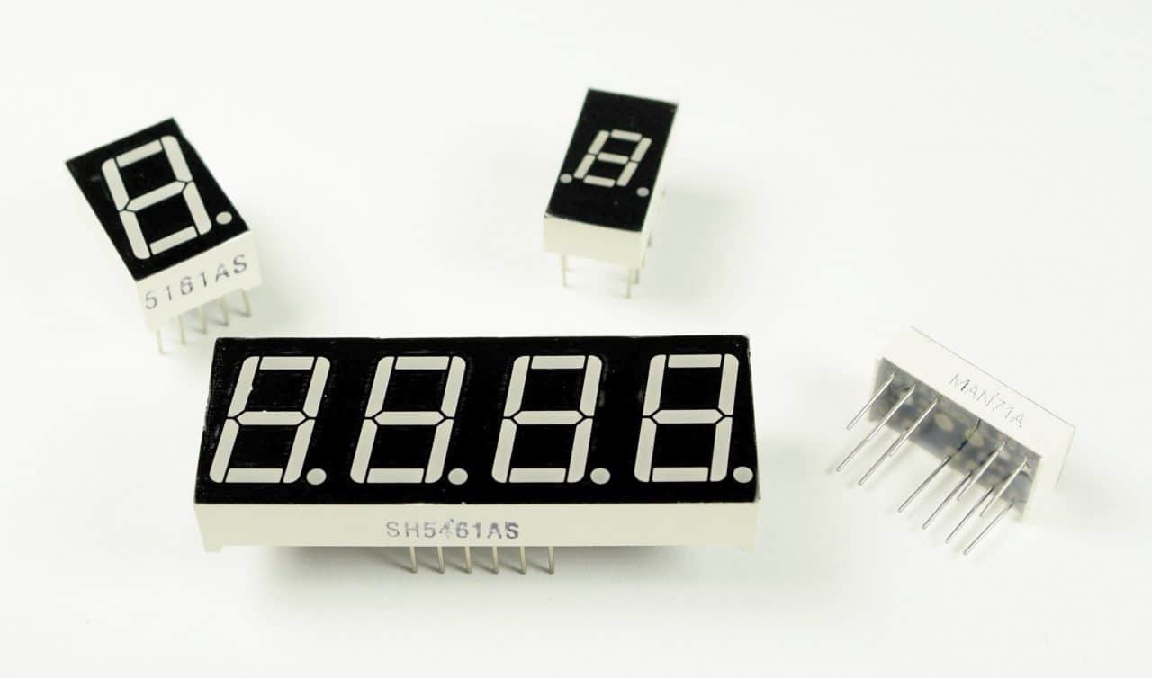
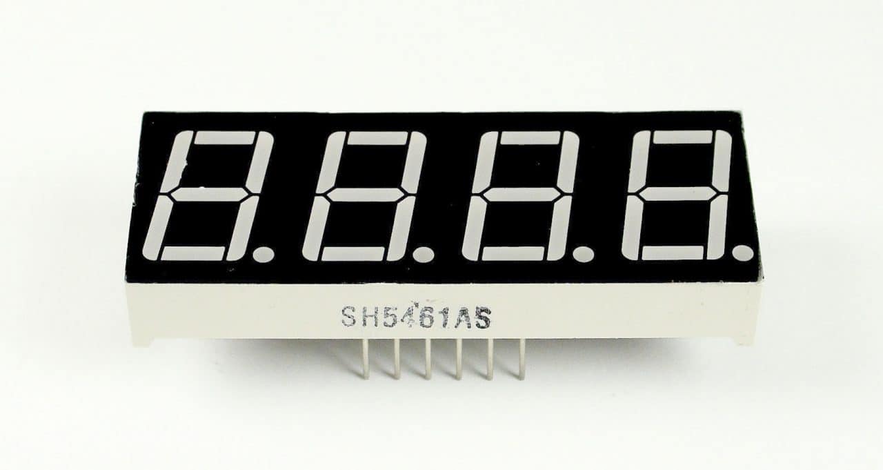
Seven segment displays come in a wide variety of sizes and colors. Red, blue, and green are the easiest colors to find. Sizes range from small 0.56 inch displays up to large 4 inch and even 6.5 inch displays. Some displays have a single digit, and others have two or four.
Before we start working with 7 segment displays, we need to understand some of the basics of LEDs and how to control them.
Watch the video for this tutorial here:
LED Basics
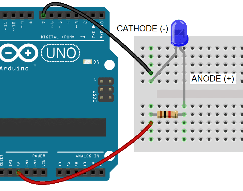
A single LED consists of two terminals, an anode and a cathode. The anode is the positive terminal and the cathode is the negative terminal:
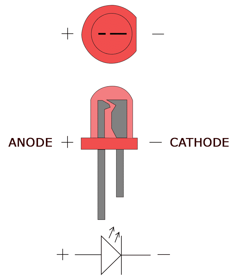
To power the LED, you connect the cathode to ground and the anode to the voltage supply. The LED can be turned on or off by switching power at the anode or the cathode.
Anode to GPIO
With the LED’s anode connected to a digital pin, the cathode is connected to ground:
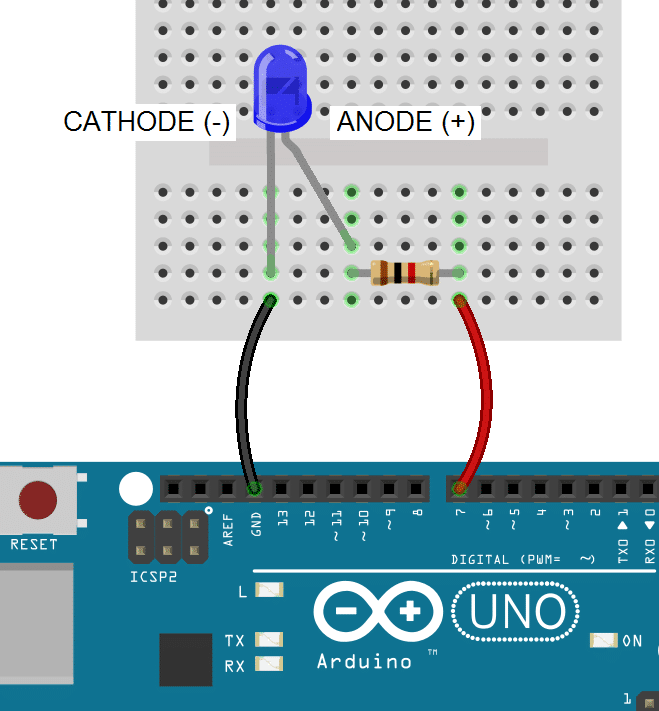
Note: All LEDs need a current limiting resistor placed on either the anode side or cathode side to prevent the LED from burning out. The resistor value will determine how bright the LED shines. 1K ohms is a good place to start, but you can calculate the ideal value with an LED resistor calculator.
To light up an LED with the anode connected to a digital pin, you set the digital pin to HIGH:
void setup(){
    pinMode(7, OUTPUT);
    digitalWrite(7, HIGH);
}

void loop(){
}
In the void setup() block, we configure GPIO pin 7 as an output with pinMode(7, OUTPUT) and drive it high with digitalWrite(7, HIGH).
Cathode to GPIO
With an LED’s cathode connected to a digital pin, the anode is connected to Vcc. To turn on the LED, the digital pin is switched LOW, which completes the circuit to ground:
In this case we drive GPIO pin 7 LOW with digitalWrite(7, LOW). This closes the circuit and allows current to flow from Vcc to ground:
void setup(){
    pinMode(7, OUTPUT);
    digitalWrite(7, LOW);
}

void loop(){
}
How 7-Segment Displays Work
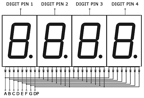
Seven segment displays consist of 7 LEDs, called segments, arranged in the shape of an “8”. Most 7-segment displays actually have 8 segments, with a dot on the right side of the digit that serves as a decimal point. Each segment is named with a letter A to G, and DP for the decimal point:
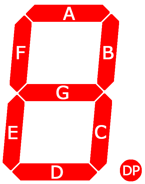
Each segment on the display can be controlled individually, just like a regular LED.
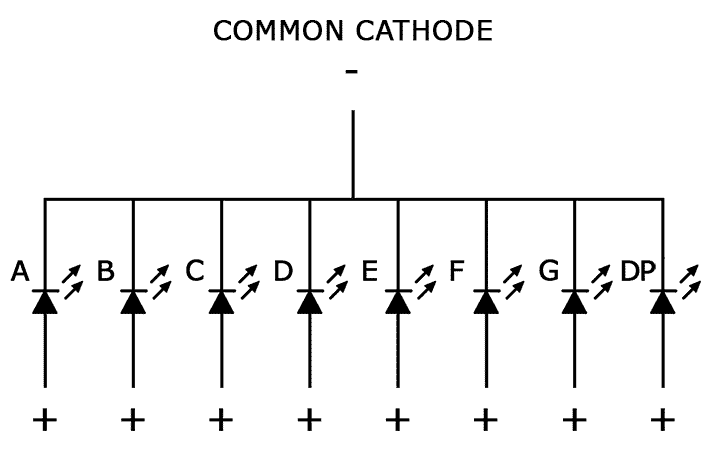
There are two types of 7-segment displays – common cathode and common anode.
Common Cathode Displays
In common cathode displays, all of the cathodes are connected to ground and individual segments are turned on and off by switching power to the anodes:
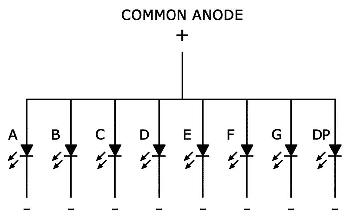
Common Anode Displays
In common anode displays, all of the anodes are connected to Vcc, and individual segments are turned on and off by switching power to the cathodes:
Connecting 7-Segment Displays to the Arduino
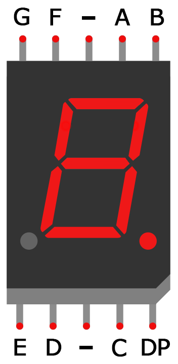
Single digit seven segment displays typically have 10 pins. Two pins connect to ground, and the other 8 connect to each of the segments. Here is a pin diagram of the popular 5161AS common cathode display:
Before you can connect your display to the Arduino, you need to know if it’s common anode or common cathode, and which pins connect to each segment. This information should be in the datasheet, but if you can’t find the datasheet or you don’t know your display’s part number, I’ll show you how to figure this out below…
How to Tell If You Have a Common Anode or Common Cathode Display
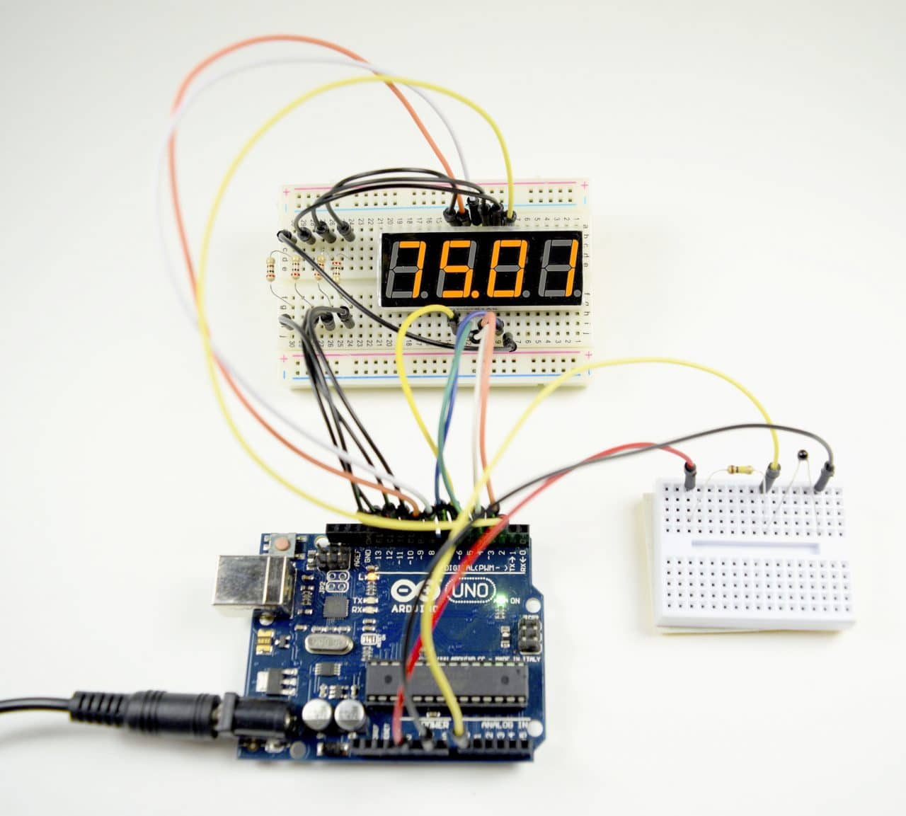
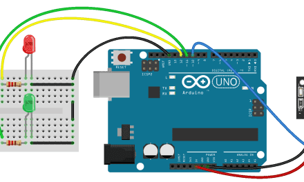
To determine if a display is common anode or common cathode, you can probe the pins with a test circuit constructed like this:
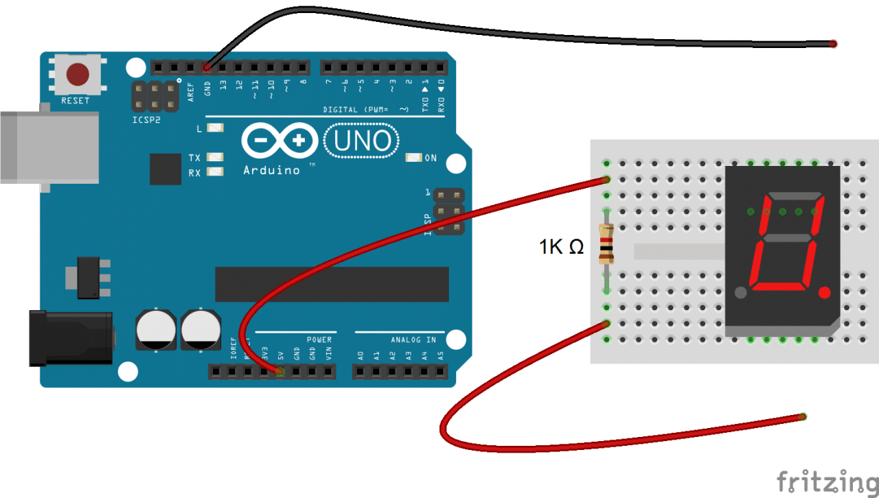
Connect the ground (black) wire to any pin of the display. Then insert the positive (red) wire into each one of the other pins. If no segments light up, move the ground wire over to another pin and repeat the process. Do this until at least one segment lights up.
When the first segment lights up, leave the ground wire where it is, and connect the positive wire to each one of the other pins again. If a different segment lights up with each different pin, you have a common cathode display. The pin that’s connected to the ground wire is one of the common pins. There should be two of these.
If two different pins light up the same segment, you have a common anode display. The pin that’s connected to the positive wire is one of the common pins. Now if you connect the ground wire to each one of the other pins, you should see that a different segment lights up with each different pin.
How to Determine the Pinout for Your Display
Now draw a diagram showing the pins on your display. With the common pin connected to the ground wire (common cathode) or positive wire (common anode), probe each pin with the other wire. When a segment lights up, write down the segment name (A-G, or DP) next to the corresponding pin on your diagram.
Connecting Single Digit Displays to the Arduino
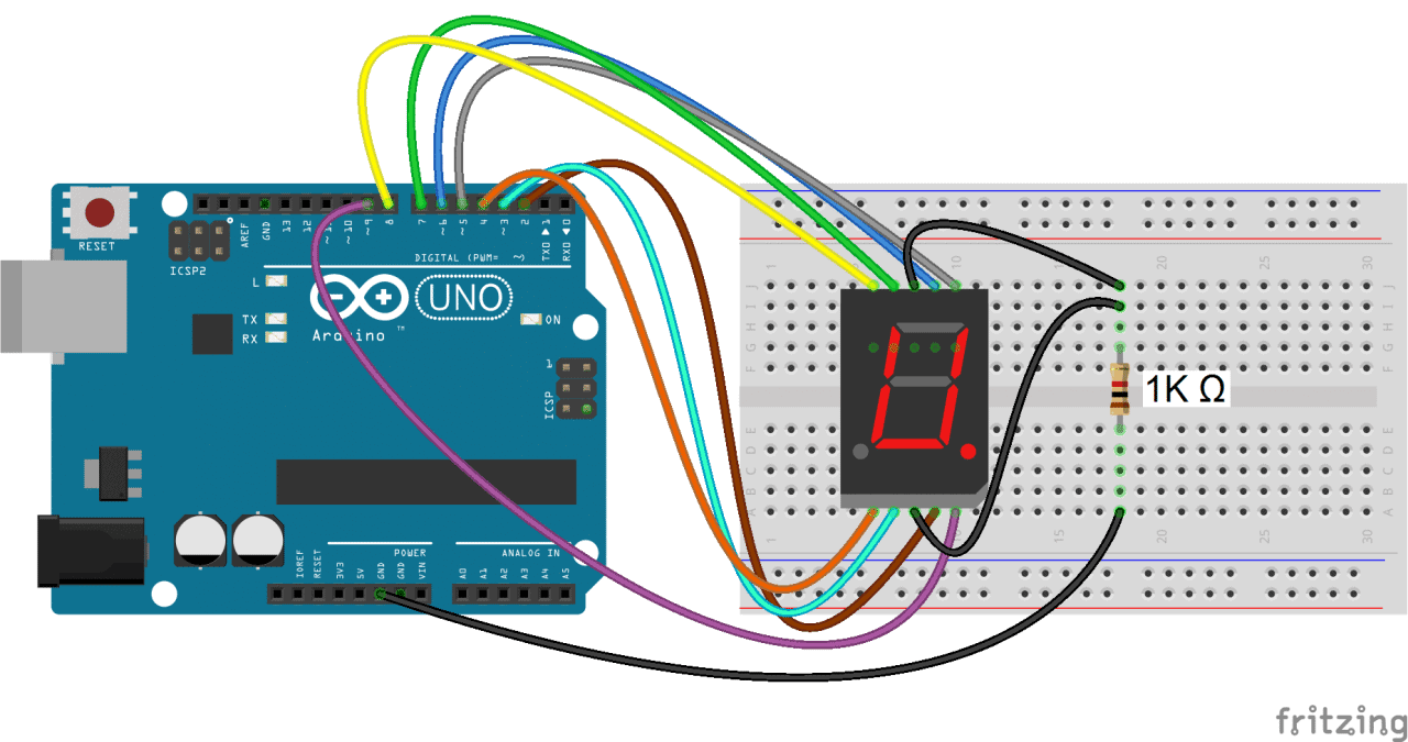
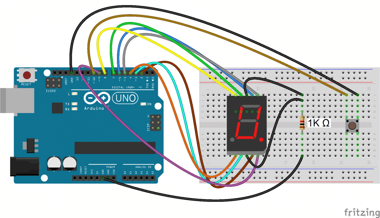
Once you have the pin layout figured out, connecting the display to an Arduino is pretty easy. This diagram shows how to connect a single digit 5161AS display (notice the 1K ohm current limiting resistor connected in series with the common pins):
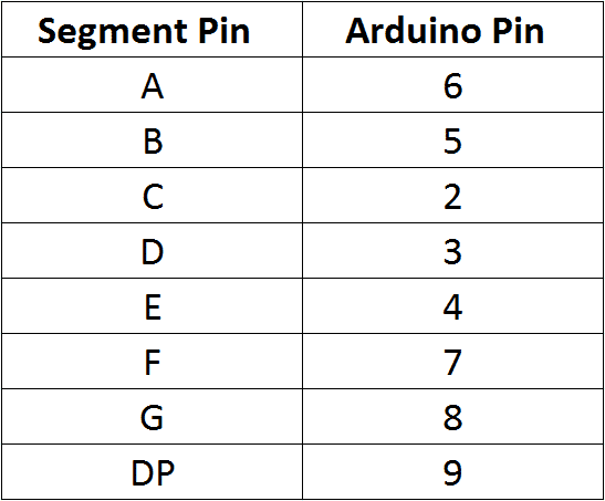
In the example programs below, the segment pins connect to the Arduino according to this table:
Programming Single Digit Displays
Install the Library
We’ll use a library called SevSeg to control the display. The SevSeg library works with single digit and multi-digit seven segment displays. You can download the library’s ZIP file from GitHub or download it here:
To install it, open the Arduino IDE, go to Sketch > Include Library > Add .ZIP Library, then select the SevSeg ZIP file that you downloaded.
Printing Numbers to the Display
This program will print the number “4” to a single digit 7-segment display:
#include "SevSeg.h"
SevSeg sevseg;

void setup(){
    byte numDigits = 1;
    byte digitPins[] = {};
    byte segmentPins[] = {6, 5, 2, 3, 4, 7, 8, 9};
    bool resistorsOnSegments = true;

    byte hardwareConfig = COMMON_CATHODE;
    sevseg.begin(hardwareConfig, numDigits, digitPins, segmentPins, resistorsOnSegments);
    sevseg.setBrightness(90);
}

void loop(){
        sevseg.setNumber(4);
        sevseg.refreshDisplay();
}
In this program, we create a sevseg object on line 2. To use additional displays, you can create another object and call the relevant functions for that object. The display is initialized with the sevseg.begin() function on line 11. The other functions are explained below:
hardwareConfig = COMMON_CATHODE – This sets the type of display. I’m using a common cathode, but if you’re using a common anode then use COMMON_ANODE instead.
byte numDigits = 1 – This sets the number of digits on your display. I’m using a single digit display, so I set it to 1. If you’re using a 4 digit display, set this to 4.
byte digitPins[] = {} – Creates an array that defines the ground pins when using a 4 digit or multi-digit display. Leave it empty if you have a single digit display. For example, if you have a 4 digit display and want to use Arduino pins 10, 11, 12, and 13 as the digit ground pins, you would use this: byte digitPins[] = {10, 11, 12, 13}. See the 4 digit display example below for more info.
byte segmentPins[] = {6, 5, 2, 3, 4, 7, 8, 9} – This declares an array that defines which Arduino pins are connected to each segment of the display. The order is alphabetical (A, B, C, D, E, F, G, DP where DP is the decimal point). So in this case, Arduino pin 6 connects to segment A, pin 5 connects to segment B, pin 2 connects to segment C, and so on.
resistorsOnSegments = true – This needs to be set to true if your current limiting resistors are in series with the segment pins. If the resistors are in series with the digit pins, set this to false. Set this to true when using multi-digit displays.
sevseg.setBrightness(90) – This function sets the brightness of the display. It can be adjusted from 0 to 100.
sevseg.setNumber() – This function prints the number to the display. For example, sevseg.setNumber(4) will print the number “4” to the display. You can also print numbers with decimal points. For example, to print the number “4.999”, you would use sevseg.setNumber(4999, 3). The second parameter (the 3) defines where the decimal point is located. In this case it’s 3 digits from the right most digit. On a single digit display, setting the second parameter to “0” turns on the decimal point, while setting it to “1” turns it off.
sevseg.refreshDisplay() – This function is required at the end of the loop section to continue displaying the number.
Count Up Timer
This simple program will count up from zero to 9 and then loop back to the start:
#include "SevSeg.h"
SevSeg sevseg;

void setup(){
    byte numDigits = 1;
    byte digitPins[] = {};
    byte segmentPins[] = {6, 5, 2, 3, 4, 7, 8, 9};
    bool resistorsOnSegments = true;

    byte hardwareConfig = COMMON_CATHODE;
    sevseg.begin(hardwareConfig, numDigits, digitPins, segmentPins, resistorsOnSegments);
    sevseg.setBrightness(90);
}

void loop(){
    for(int i = 0; i < 10; i++){
        sevseg.setNumber(i, i%2);
        delay(1000);
        sevseg.refreshDisplay();
        }
}
The code is similar to the previous sketch. The only difference is that we create a count variable “i” in the for statement on line 16 and increment it one number at a time.
The sevseg.setNumber(i, i%2) function prints the value of i. The i%2 argument divides i by 2 and returns the remainder, which causes the decimal point to turn on every other number.
The count up timer is a nice way to demonstrate the basics of how to program the display, but now let’s try to make something more interesting.
Rolling Dice
This example consists of a push button and a single 7 segment display. Every time the push button is pressed and held, the display loops through numbers 0-9 rapidly. Once the button is released, the display continues to loop for a period of time almost equal to the time the button was pressed, and then displays a number along with the decimal point to indicate the new number.
To build the circuit (with the 5161AS display), connect it like this:
Then upload this program to the Arduino:
#include "SevSeg.h"
SevSeg sevseg;

const int  buttonPin = 10;    // the pin that the pushbutton is attached to
int buttonState = 0;          // current state of the button
int lastButtonState = LOW;    // previous state of the button
int buttonPushCounter = 0;    // counter for the number of button presses
long counter = 0;
long max_long_val = 2147483647L;

void setup(){
  byte numDigits = 1;
  byte digitPins[] = {};
  byte segmentPins[] = {6, 5, 2 , 3, 4 , 7, 8, 9};
  bool resistorsOnSegments = true;

  byte hardwareConfig = COMMON_CATHODE;
  sevseg.begin(hardwareConfig, numDigits, digitPins, segmentPins, resistorsOnSegments);
  sevseg.setBrightness(90);

  pinMode(buttonPin, INPUT_PULLUP);
  Serial.begin(9600);
  lastButtonState = LOW;
}

void loop(){
  buttonState = digitalRead(buttonPin);
  if(buttonState == HIGH){
    buttonState = LOW;
    }

  else
   buttonState = HIGH;

  if(buttonState == HIGH){
     Serial.println("on");
     lastButtonState = HIGH;
     buttonPushCounter++;
     if(counter < max_long_val)
       counter++;
     buttonPushCounter %= 9;
     sevseg.setNumber(buttonPushCounter, 1);
     sevseg.refreshDisplay();
     delay(100 - (counter%99));
     }

  else{
     Serial.println("off");
     if(lastButtonState == HIGH){
       Serial.println("in");
       buttonPushCounter++;
       buttonPushCounter %= 7;
       if(buttonPushCounter == 0)
         buttonPushCounter = 1;
       counter--;
       sevseg.setNumber(buttonPushCounter, 1);
       sevseg.refreshDisplay();
       delay(100 - (counter%99));
       if(counter == 0){
         lastButtonState = LOW;
         sevseg.setNumber(buttonPushCounter, 0);
         sevseg.refreshDisplay();
         }
       }
     }
}
4 Digit 7-Segment Displays
So far we have only worked with single digit 7-segment displays. To display information such as the time or temperature, you will want to use a 2 or 4 digit display, or connect multiple single digit displays side by side.
In multi-digit displays, one segment pin (A, B, C, D, E, F, G, and DP) controls the same segment on all of the digits. Multi-digit displays also have separate common pins for each digit – these are the digit pins. You can turn a digit on or off by switching the digit pin.
I’m using a 4 digit 7-segment display with the model number 5641AH, but the wiring diagrams below will also work with the 5461AS.
Here is a diagram showing the pinout of these displays:
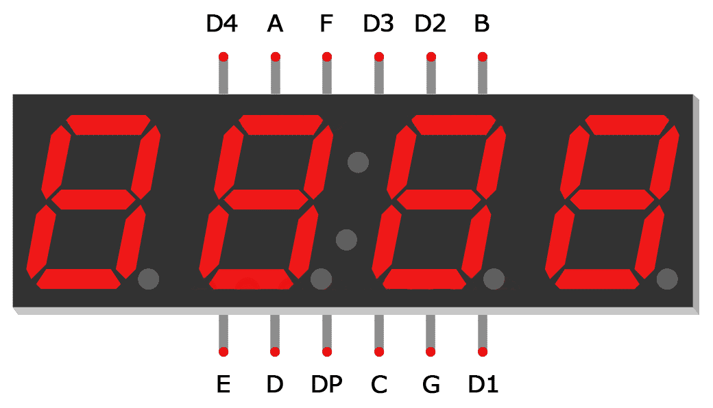
The digit pins D1, D2, D3 and D4 need to be connected to current limiting resistors, since they are the common terminals of the digits. The connections are shown below:
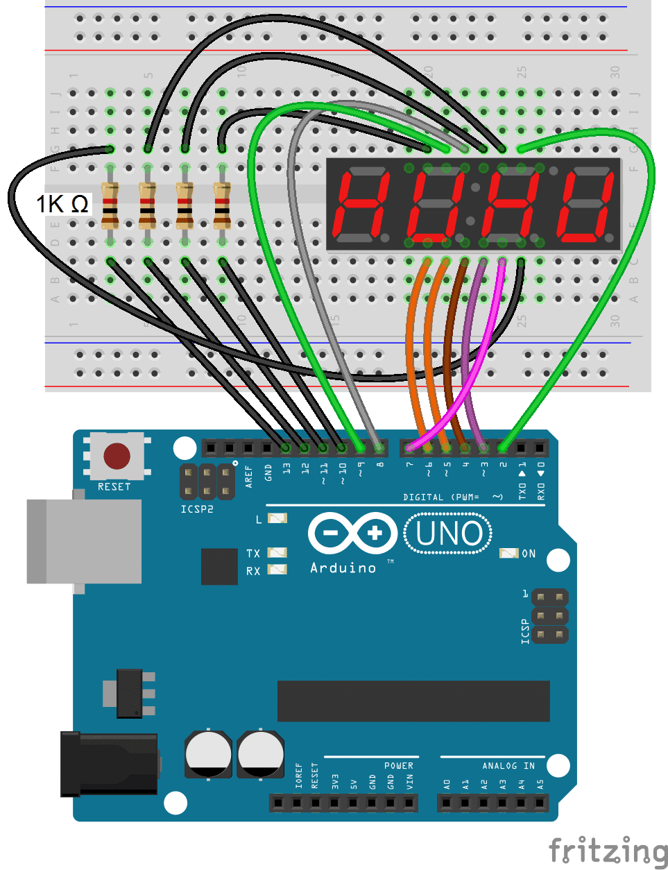
This simple program will print the number “4.999” to the display:
#include "SevSeg.h"
SevSeg sevseg;

void setup(){
  byte numDigits = 4;
  byte digitPins[] = {10, 11, 12, 13};
  byte segmentPins[] = {9, 2, 3, 5, 6, 8, 7, 4};

  bool resistorsOnSegments = true;
  bool updateWithDelaysIn = true;
  byte hardwareConfig = COMMON_CATHODE;
  sevseg.begin(hardwareConfig, numDigits, digitPins, segmentPins, resistorsOnSegments);
  sevseg.setBrightness(90);
}

void loop(){
    sevseg.setNumber(4999, 3);
    sevseg.refreshDisplay();
}
In the code above, we set the number of digits in line 5 with byte numDigits = 4.
Since multi-digit displays use digit pins, we also need to define which Arduino pins will connect to the digit pins. Using byte digitPins[] = {10, 11, 12, 13} on line 6 sets Arduino pin 10 as the first digit pin, Arduino pin 11 to the second digit pin, and so on.
To print numbers with a decimal point, we set the second parameter in sevseg.setNumber(4999, 3) to three, which puts it three decimal places from the right most digit.
Displaying Sensor Data
Now let’s read the temperature from a thermistor and display it on a 4 digit display.
Connect the circuit like this:
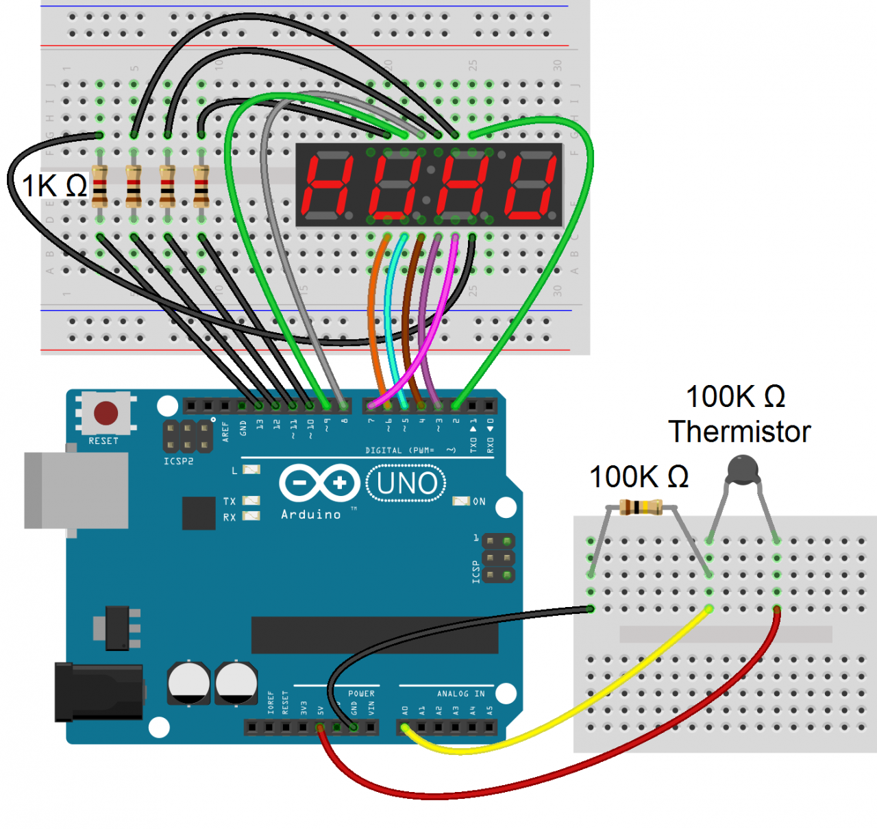
If you want to learn more about thermistors, check out our tutorial on using a thermistor with an Arduino.
Once everything is connected, upload this code to the Arduino:
#include "SevSeg.h"
SevSeg sevseg;

int ThermistorPin = 0;
int Vo;
float R1 = 10000;
float logR2, R2, T;
float c1 = 1.009249522e-03, c2 = 2.378405444e-04, c3 = 2.019202697e-07;

void setup() {
  byte numDigits = 4;
  byte digitPins[] = {10, 11, 12, 13};
  byte segmentPins[] = {9, 2, 3, 5, 6, 8, 7, 4};
  bool resistorsOnSegments = true;
  byte hardwareConfig = COMMON_CATHODE;

  sevseg.begin(hardwareConfig, numDigits, digitPins, segmentPins, resistorsOnSegments);
}

void loop() {
  Vo = analogRead(ThermistorPin);
  R2 = R1 * (1023.0 / (float)Vo - 1.0);
  logR2 = log(R2);
  T = (1.0 / (c1 + c2 * logR2 + c3 * logR2 * logR2 * logR2));
  T = T - 273.15;
  T = (T * 9.0) / 5.0 + 32.0; //Comment out for Celsius

  static unsigned long timer = millis();

  if (millis() >= timer) {
    timer += 300;
    sevseg.setNumber(T, 2);
  }

  sevseg.refreshDisplay();
}
This will display the temperature in Fahrenheit on the 7-segment display. To display the temperature in Celsius, comment out line 28.
By itself, the display will update every time the temperature changes even slightly. This creates an annoying flickering. In order to deal with this, we introduce a timer mechanism, where we only read the value from the thermistor every 300 milliseconds (lines 30 to 34).
The temperature variable “T” is printed to the display on line 35 with sevseg.setNumber(T, 2, false).
Hopefully this article should be enough to get you started using seven segment displays. If you want to display readings from other sensors, the example program above can easily be modified to do that. If you have any questions or trouble setting up these circuits, feel free to leave a comment below.


Thanks for these tutorials about using the NTC probe with the Arduino.
What I would also like is using setpoint buttons to control a relais.
Many thanks.
Learn how to build this without Arduino for just £3. Search “odonodesign temperature” on google to find out how.
Thank you so much! FINALLY got it working, now I can tinker all I want :)
This is by far the clearest explanation out there.
kid wow https://t.co/DiuUrfMbzF
Lovely tutorial got it to work easily. I have 1 problem which is that I need to let the display count down with all 4 numbers displayed at once. Right now with the count up code above because of the `delay(1000);` it displays 1 number at a time. It starts with the first number on the display then goes on to the next until it went through all 4 and it will go back to the first. Is there a way around it to display all 4 digits at once while still counting down in seconds?
i have this same problem
Shouldn’t you use 8 resistors, one on each segment channel instead of the ground? Like this , a single segment used will burn brighter than all 8 segments used.
When you put a resistor on each segment the resistance goes up a fraction for every segment used.
Hi ,good project ,what is with negative temperature ?How can put “–” mark?
One resistor is enough. The led on each segment are not in the same state (ON/OFF)per time no matter what you wrote. The led change state at a very fast speed not visible to the eye(Persistent of Vision,POV). This has been taking care off in the library downloaded.
No, the original poster is correct. The current of all the LEDS is shared by the single resistor, so the 5mA allowed by the 1K resistor (assuming 5V) is shared among all the segments. So the amount of current allocated to each LED (and thus its brightness) is dependent on the number of LEDs illuminated by the digit.
It has nothing to do with persistence of vision. It has to do with ohm’s law. So a 1 would be brighter than an 8. You should have like a 220 ohm resistor at every anode.
This was a great help, thanks!
Nice and simple explanation thanks. How would this work for positions of stepper motors on a CNC having three separate displays one each for x, y and z axis?
Thanks , my Friends for review.
i have problem with rolling dice, i want to print numbers (0, 30) in 2 digit 7 segment screen i i dont know what to change in code.
in 7 segment display it has to count 0-9 then blink 9 three times then reverse from 9-0
i need a code, please send it .
A wonderful tutorial and library. My question is, in case of 4 digits common cathode display, the cathodes of digits are directly connected to arduino pins, which i hope turn to LOW to sink an display the corresponding LEDs. However in most projects it is advisable to use an NPN transistor on the common cathod pins to sink high currents. The base of transistor then needs to be HIGH to activate the digit. How can we connect this configuration using this library? or there is another Library for that.
could you please explain what is the mean by below problem from compiler??
Arduino: 1.8.2 (Windows 10), Board: “Arduino Nano, ATmega328″
WARNING: Category ” in library UIPEthernet is not valid. Setting to ‘Uncategorized’
E:\Robot level\ARDUINOOOO\seven\seven.ino:2:20: fatal error: SevSeg.h: No such file or directory
#include “SevSeg.h”
^
compilation terminated.
exit status 1
Error compiling for board Arduino Nano.
This report would have more information with
“Show verbose output during compilation”
option enabled in File -> Preferences.
ermmm… i tried to run this website’s code on arduino, but it gave me an error message saying”exit status 1
SevSeg.h: No such file or directory”, and it highlighted the command”
#include “SevSeg.h” “. what am I supposed to do with this
I have got the same problem :/
https://www.arduino.cc/en/Guide/Libraries
try change from #include “SevSeg.h” to #include
try change from #include “SevSeg.h” to “#include ” (without quote)
Sketch, include library, manage libraries, search up SevSeg, install it
There is 2 pin COM that used 1 or 2 at once ?
Hello!
Thank you very much, very good.
My question is that the figure shows a resistance of 100 kohm, but in the program line 14: “float R1 = 10000 ;,” which is only 10kohm. Why is this so?
‘To display the temperature in Celsius, comment out line 28.’
Line 26 not 28
you need to add the file to the library the only way i know if you have downloaded the arduino IDE software: https://www.arduino.cc/en/Guide/Libraries
I like this seven segment tutorial. Would you happen to have a program using DS1307 and displayed in six seven segment display (hours, minutes, seconds)?
hello, I tried use above code with lm35 sensor but it didnt work. can you suggest me any example for my project?
Here you can watch my version of 7 segment indicator project (I mean the code):
https://positiveknight.com/arduino-project-4-countdown-on-indicator/
hola probe varios sketch y en ninguno logro hacer que me funcione esta libreria sevseg me marca cualquier cosa y en cualquier digito el display de 7 seg 4 digito anodo comun que utilizo lo probe con otra estructura de lectura y funciona perfecto. pero con sevseg no inclusive probe todas las configuraciones y nada. adjunto el sketch espero puedan ayudarme desde ya muchisimas gracias.
include
SevSeg sevseg;
void setup(){
byte numDigits = 2;
byte digitPins[] = {10,11};
byte segmentPins[] = {4, 2, 6, 8, 9, 3, 5, 7};
bool resistorsOnSegments = false;
byte hardwareConfig = COMMON_ANODE;
sevseg.begin(hardwareConfig, numDigits, digitPins, segmentPins, resistorsOnSegments);
sevseg.setBrightness(90);
}
void loop(){
sevseg.setNumber(1);
sevseg.refreshDisplay();
}
con esta configuracion en el display aparece esto: E. 8.8.
Great project. I have a 3 digit display but when the program calculates the Temperature it has 2 decimal characters, this means there are 4 characters altogether which is interpreted as garbage on a 3 digit display. How do I drop off one character before sending it to the 3 digit display, please
Hi, I have the same problem. Very similar code to the above; I have one digit that always shows “8.” (all led lit). Any help what to do here?
Many thanks
@marce: I could solve it, for me it was the “resistorsOnSegment” that I should have put to true. Once I did that, it worked.
I have another problem: For a single digit, sevseg.setChars does not word – it always shows “-“, what indicates an illegal input. I tried String, char[], char, overwrite variable with strcpy, …… nothing works.
Appreciate some tips.
I also noticed the 1 was brighter than the 8. I set resistorsOnSegment to false and it’s perfect, but my DP is not working and I don’t know how to access the colon in the middle.
Hola que tengo que modificar en la linea 28 para mostrar la temperatura en Celsius , me pueden ayudar .
I download the SevSeg library. In the SevSeg.cpp file in 147. row are this comment
//If you use current-limiting resistors on your segment pins instead of the
// digit pins, then set resOnSegments as true.
In 4 DIGIT 7-SEGMENT DISPLAYS session in code example the bool resistorsOnSegments set true.
But in the figure above, the resistors are connected to the digit pins.
Is this correct?
Thanks answer!
Since this program will multiplex the segments and digits, it must scan fast enough so as NOT to appear to flicker.
How much time is left for the program to do other things like calculation, motor control etc….?
Or is there a better way to drive the display or a better display to use?
Thanks,
Dennis
Would like to use RTC DS3231 on 7 seg. Hours and Minute display. Please give me a hand on this.
Thank you for the great tutorial. It was very useful for me :)
very nice tutorial.
thank you.
I made it and is working very well. the only thing, on my display I’ve got the temperature as 0.T the decimal point was in the wrong place.
but, I’ve changed this line, from:
T = (T – 273.15);
to this one:
T = (T – 273.15)*100;
and now, I have the temperature OK.
https://www.amazon.ca/photos/share/gtExI1pGtEZf79Xza4XFu25NY5K7iJUqT0kqjn0LjgM
here is the code I used:
//
#include “SevSeg.h”
SevSeg sevseg;
int ThermistorPin = 0;
int Vo;
float R1 = 10000;
float logR2, R2, T;
float c1 = 1.009249522e-03, c2 = 2.378405444e-04, c3 = 2.019202697e-07;
void setup() {
byte numDigits = 4;
byte digitPins[] = {10, 11, 12, 13};
byte segmentPins[] = {9, 2, 3, 5, 6, 8, 7, 4};
bool resistorsOnSegments = true;
byte hardwareConfig = COMMON_ANODE;
bool updateWithDelays = false; // Default ‘false’ is Recommended
bool leadingZeros = false; // Use ‘true’ if you’d like to keep the leading zeros
bool disableDecPoint = false; // Use ‘true’ if your decimal point doesn’t exist or isn’t connected. Then, you only need to specify 7 segmentPins[]
//digitPins is an array that stores the arduino pin numbers that the digits are connected to.
//Order them from left to right.
//segmentPins is an array that stores the arduino pin numbers that the segments are connected to.
//Order them from segment a to g, then the decimal place (if it’s connected).
sevseg.begin(hardwareConfig, numDigits, digitPins, segmentPins, resistorsOnSegments, updateWithDelays, leadingZeros, disableDecPoint);
}
void loop() {
Vo = analogRead(ThermistorPin);
R2 = R1 * (1023.0 / (float)Vo – 1.0);
logR2 = log(R2);
T = (1.0 / (c1 + c2 * logR2 + c3 * logR2 * logR2 * logR2));
T = (T – 273.15)*100;
//T = (T * 9.0) / 5.0 + 32.0; //Comment out for Celsius
static unsigned long timer = millis();
if (millis() >= timer) {
timer += 300;
sevseg.setNumber(T, 2);
}
sevseg.refreshDisplay();
}
it says that: artificial>:(.text.startup+0x5c): undefined reference to `SevSeg::SevSeg()’
C:\Users\user\AppData\Local\Temp\ccSmdGuM.ltrans0.ltrans.o: In function `setup’:
E:\Προγράμματα\Arduino\7-Segment Screen/7-Segment Screen.ino:18: undefined reference to `SevSeg::begin(unsigned char, unsigned char, unsigned char const*, unsigned char const*, bool, bool, bool, bool)’
E:\Προγράμματα\Arduino\7-Segment Screen/7-Segment Screen.ino:19: undefined reference to `SevSeg::setBrightness(int)’
C:\Users\user\AppData\Local\Temp\ccSmdGuM.ltrans0.ltrans.o: In function `loop’:
E:\Προγράμματα\Arduino\7-Segment Screen/7-Segment Screen.ino:42: undefined reference to `SevSeg::setNumber(long, signed char, bool)’
E:\Προγράμματα\Arduino\7-Segment Screen/7-Segment Screen.ino:43: undefined reference to `SevSeg::refreshDisplay()’
E:\Προγράμματα\Arduino\7-Segment Screen/7-Segment Screen.ino:56: undefined reference to `SevSeg::setNumber(long, signed char, bool)’
E:\Προγράμματα\Arduino\7-Segment Screen/7-Segment Screen.ino:57: undefined reference to `SevSeg::refreshDisplay()’
E:\Προγράμματα\Arduino\7-Segment Screen/7-Segment Screen.ino:61: undefined reference to `SevSeg::setNumber(long, signed char, bool)’
E:\Προγράμματα\Arduino\7-Segment Screen/7-Segment Screen.ino:62: undefined reference to `SevSeg::refreshDisplay()’
collect2.exe: error: ld returned 1 exit status
exit status 1
Compilation error: exit status 1
How can i do that correct?
Learn how to build this without Arduino for just £3. Search “odonodesign temperature” on google to find out how.