
In this article, we’re going to learn how to detect tilt by connecting two different types of tilt sensors to the Arduino. Accelerometers are the most accurate way to detect tilt, but for some projects you don’t need such high accuracy. Tilt sensors can’t measure the actual angle of tilt like accelerometers can. They can only detect if the sensor is tilted or not. Tilt sensors are commonly used on 4X4 trucks and boats to notify the driver when the vehicle could roll over or capsize.

Watch the video for this tutorial here:
How Tilt Sensors Work
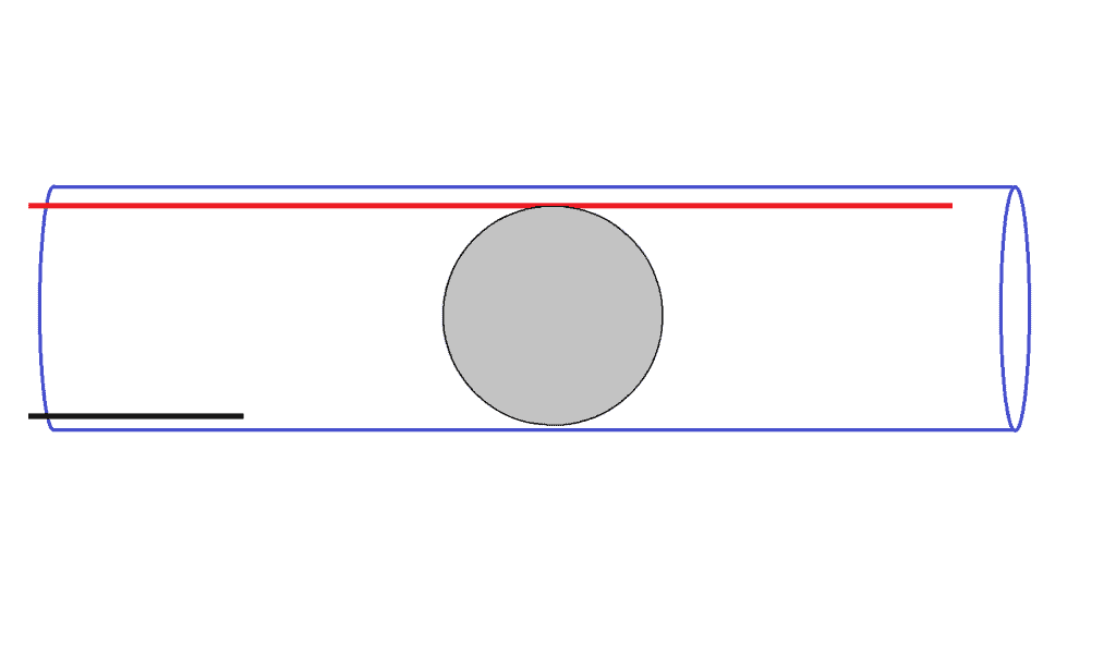
Tilt sensors are made up of a plastic or glass tube, with two pieces of wire and a metal ball inside:
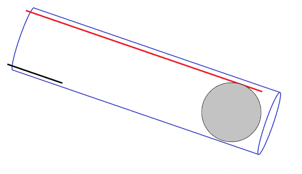
When the tube is tilted forward, the ball rolls forward and only contacts one wire.
When the tube is tilted backwards, the ball rolls back and contacts both wires.
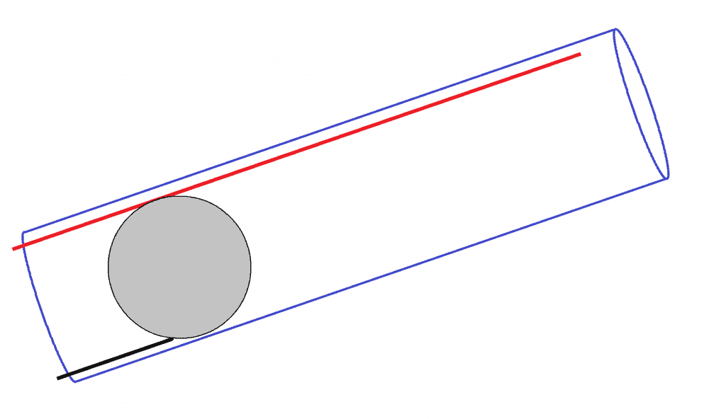
This allows current to flow between the two wires. We can detect this high or low signal with the Arduino to determine if the sensor is tilted or not.
We’re going to be working with two common tilt sensors, the Keyes KY-020 tilt switch, and the Keyes KY-017 mercury tilt switch.
Keyes KY-017 Mercury Tilt Switch
The Keyes KY-017 mercury tilt switch has a small drop of liquid mercury inside a glass bulb:
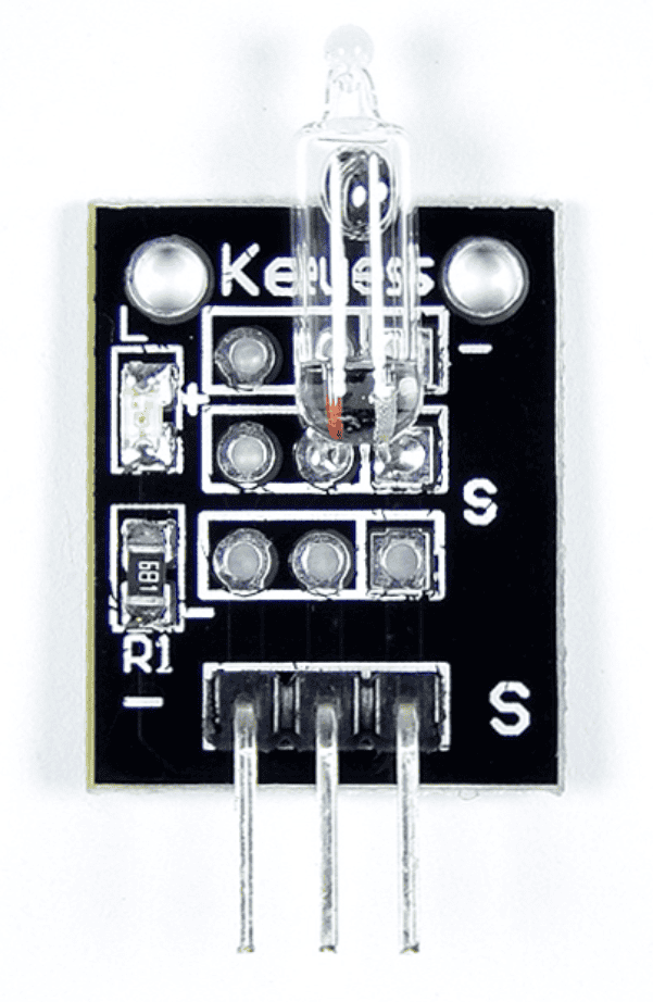
When the sensor is tilted backwards, the mercury contacts two electrodes inside the glass bulb and allows current to flow between them. When the sensor is tilted forward, the mercury loses contact with one of the electrodes and current stops flowing.
Mercury tilt switches are more sensitive and reliable than metal ball tilt sensors. But mercury is toxic, so don’t use them in high impact situations where there is a risk of breaking the glass. Here’s a diagram that shows the pins of the Keyes KY-017 mercury tilt switch:
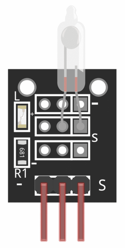
The pin with the S next to it is the signal pin. The pin with the minus sign (-) is the ground pin. And the middle pin is the Vcc pin.
Keyes KY-020 Tilt Switch
The Keyes KY-020 tilt switch has a blue chamber with a small metal ball inside that rolls back and forth:
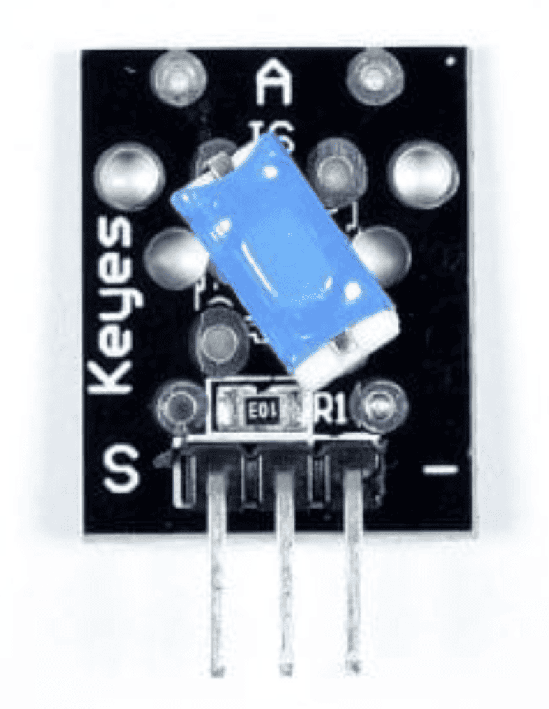
Depending on the orientation of the sensor, the ball causes two electrical contacts inside the chamber to be either open or closed. The pin with the S is the signal pin. The middle pin is the Vcc pin. And the pin with the minus sign (-) is the ground pin.
Example Project
Let’s build a tilt sensor circuit that turns on a red LED when the sensor is tilted forward, and turns on a green LED when it’s tilted backwards.
Here are the parts you will need:
- Arduino Uno
- Jumper wires
- Breadboard
- Two LEDs
- Two 220 Ohm resistors
- Keyes KY-020 tilt switch or
- Keyes KY-017 mercury tilt switch
The Keyes KY-020 tilt switch and the Keyes KY-017 mercury tilt switch have different pin layouts, so connect the circuit according to the sensor you have.
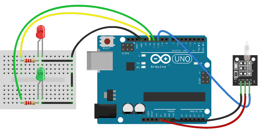
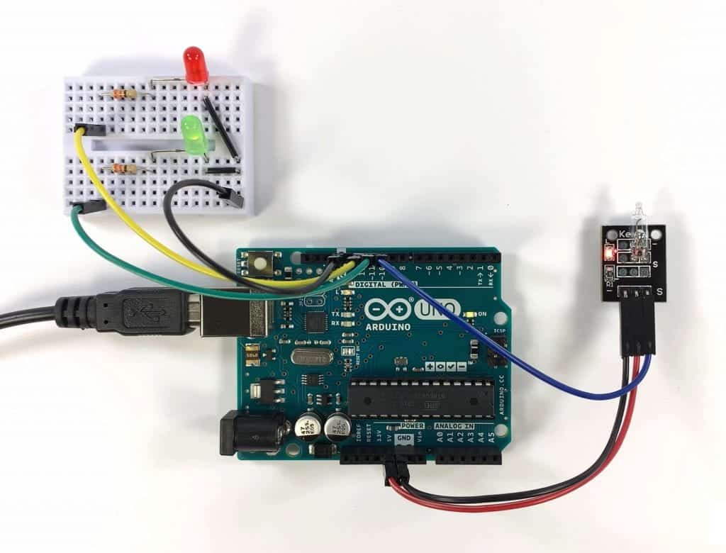
Follow this wiring diagram to connect the Keyes KY-017 mercury tilt switch to the Arduino:
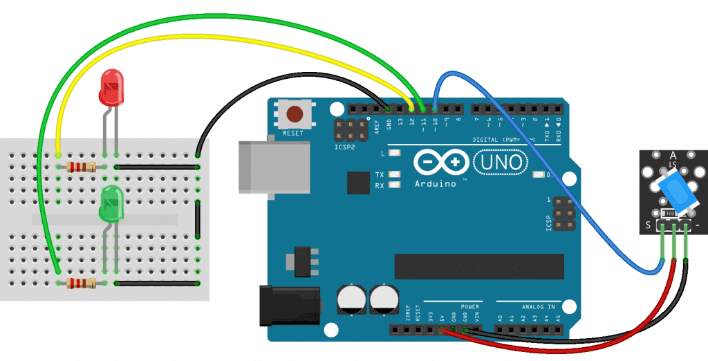
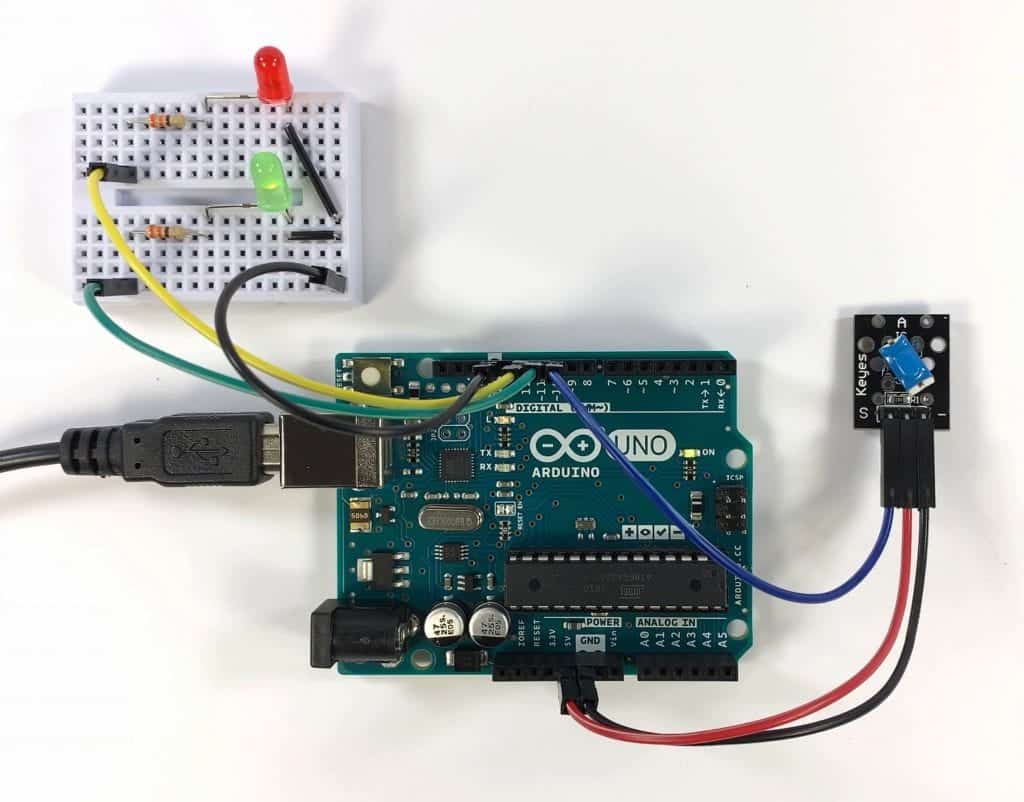
Follow this diagram to connect the Keyes KY-020 tilt switch:
How to Program a Keyes KY-017 Mercury Tilt Switch
Once the circuit is connected, upload this code to the Arduino:
int sensorPin = 10;
int forwardLED = 12;
int reverseLED = 11;

void setup() {
  pinMode(sensorPin, INPUT);
  pinMode(forwardLED, OUTPUT);
  pinMode(reverseLED, OUTPUT);
}

void loop() {
  int read = digitalRead(sensorPin);

  if (read == HIGH) {
    digitalWrite(forwardLED, HIGH);
    digitalWrite(reverseLED, LOW);
  }

  if (read == LOW) {
    digitalWrite(reverseLED, HIGH);
    digitalWrite(forwardLED, LOW);
  }
}
Explanation of the Code
At the top of the sketch, we declare variables for the pins. One variable is called sensorPin, and is set equal to pin 10. Another variable is called forwardLED and is set equal to pin 12. The third variable is called reverseLED and is set equal to pin 11.
In the setup() section we set the pin mode for each pin variable. The sensorPin is an input, the forwardLED pin is an output, and the reverseLED pin is an output as well.
In the loop() section, we take a digital read from the sensorPin, and store it in a local variable called read. Next we use two if statements to control what happens when the sensorPin goes high and low.
Mercury tilt switches output a high signal when tilted forward, and a low signal when tilted backwards. So the first if statement says “if read equals HIGH, then digital write the forwardLED pin HIGH, and digital write the reverseLED pin LOW“. This turns the red LED on when the sensor is tilted forward.
The second if statement says “if read equals LOW, then digital write the reverseLED pin HIGH, and digital write the forwardLED pin LOW“. This turns on the green LED when the sensor is tilted backwards.
Once you connect the tilt sensor and LEDs to the Arduino and upload the code, you should see the red LED turn on when the sensor is tilted forward. When the sensor is tilted backwards, the green LED should turn on:
LEDs are just a good way to demonstrate what’s happening with the Arduino’s output pins. Instead of an LED, you can control any other device that’s activated by a 5V high or low signal.
How to Program a Keyes KY-020 Tilt Switch
If you’re using the Keyes KY-020 metal ball tilt switch, the code is similar. But metal ball tilt switches output a low signal when tilted forward, and a high signal when tilted back. This is opposite from the mercury tilt switch.
Once the circuit is connected, upload this code to the Arduino:
int sensorPin = 10;
int forwardLED = 12;
int reverseLED = 11;

void setup() {
  pinMode(sensorPin, INPUT);
  pinMode(forwardLED, OUTPUT);
  pinMode(reverseLED, OUTPUT);
}

void loop() {
  int read = digitalRead(sensorPin);

  if (read == HIGH) {
    digitalWrite(forwardLED, HIGH);
    digitalWrite(reverseLED, LOW);
  }

  if (read == LOW) {
    digitalWrite(reverseLED, HIGH);
    digitalWrite(forwardLED, LOW);
  }
}
Explanation of the Code
The code is almost identical to the mercury tilt switch. The only differences are the conditions of the if statements. Instead of writing the forwardLED pin HIGH when the sensorPin is HIGH, we need to write the forwardLED pin HIGH when the sensorPin is LOW. Also, instead of writing the reverseLED pin HIGH when the sensorPin is LOW, we need to write the reverseLED pin HIGH when the sensorPin is HIGH.
After connecting the tilt sensor and uploading the code, you should see that tilting the sensor forward lights up the red LED, and tilting it backwards lights up the green LED:
The KY-020 tilt sensor is less responsive than the mercury switch and it needs more angle to get the ball to roll around. So it could be better suited for applications where the tilt angle is greater.
Thanks for reading! Be sure to leave a comment if you have any questions or have trouble setting this up…


