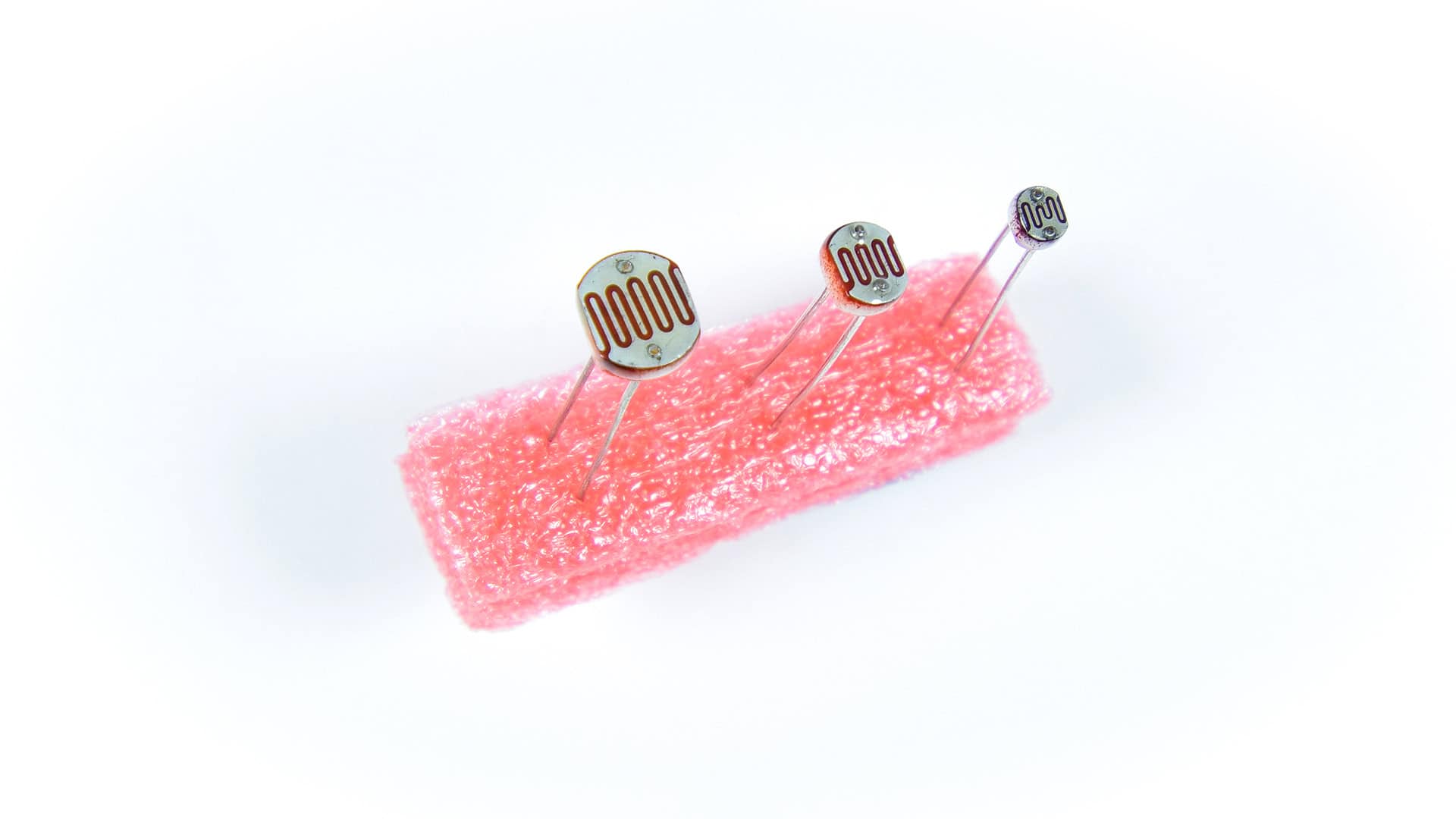
Photoresistors are analog sensors that can measure light. They are light dependent resistors that change resistance with the amount of light that hits the sensor.

Photoresistors are perfect for making light controlled switches. One common application of photoresistors is to control 5 volt relays to switch on a light bulb when it gets dark. They are also used to track daylight in weather stations and environmental monitoring systems.
Watch the video for this tutorial here:
How Photoresistors Work
Photoresistors have two separate electrodes on the sensing element. The squiggly red line is a layer of semiconductive material between the two electrodes:
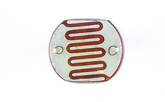
The semiconductive material increases in conductivity when more light hits it. When the conductivity increases, the resistance decreases. Therefore the resistance of a photoresistor decreases with increasing light intensity. Conversely, the resistance of a photoresistor increases with decreasing light intensity.
How to Setup a Photoresistor on the Arduino
The Arduino can’t measure resistance directly, it can only measure voltage. So we have to use a voltage divider to connect photoresistors to the Arduino. Here’s a schematic of the photoresistor voltage divider circuit we are going to build:
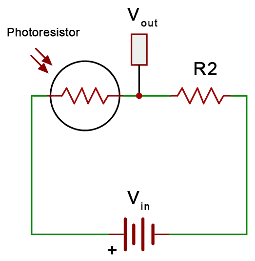
The output voltage (Vout) of the voltage divider changes when the resistance of the photoresistor changes. With no light hitting the photoresistor, the resistance of the photoresistor is high, so the output voltage is low. When light hits the photoresistor, the resistance decreases and the output voltage increases.
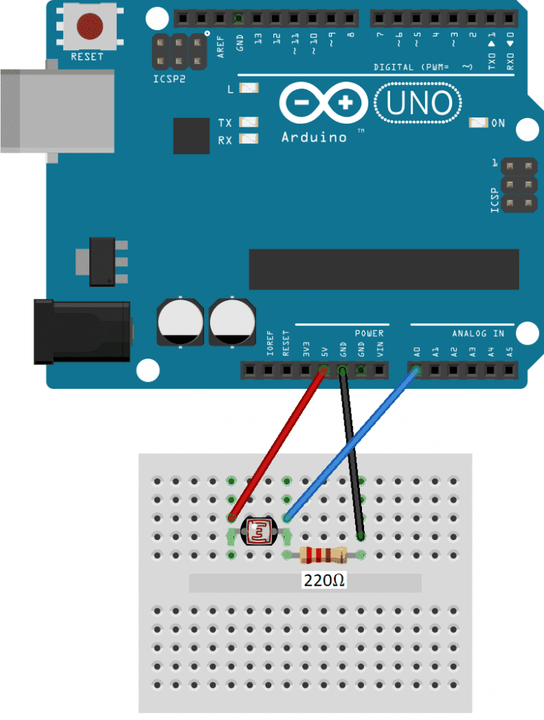
These are the parts you will need to connect a photoresistor to an Arduino:
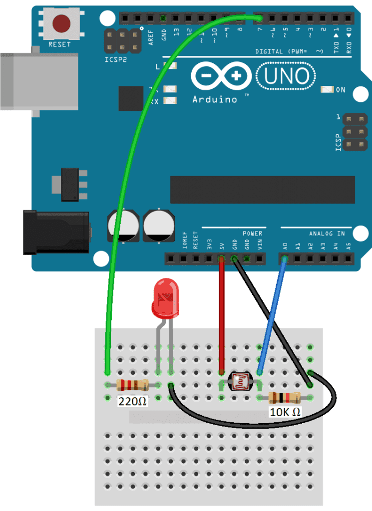
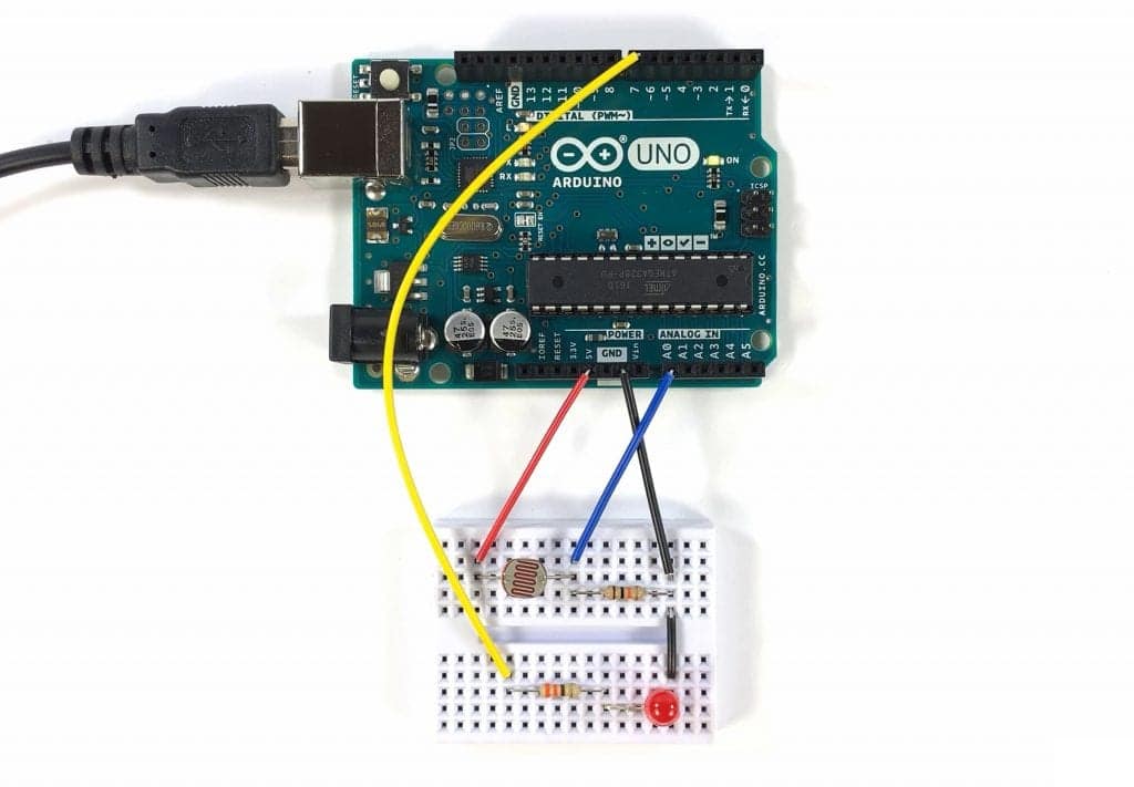
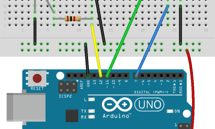
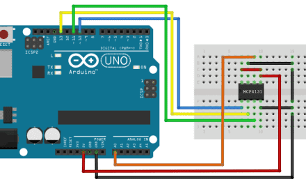
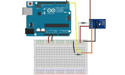
Follow this wiring diagram to connect the photoresistor voltage divider to the Arduino:
How to Program a Photoresistor on the Arduino
Now let’s look at a sketch that will output the raw light readings from the photoresistor to the serial monitor. Once the circuit is connected, upload this code to the Arduino:
int photoPin = A0;

void setup() {
  Serial.begin(9600);
}

void loop() {
  int light = analogRead(photoPin);
  Serial.println(light);
  delay(100);
}
Explanation of the Code
First, we declare an int variable called photoPin and set it equal to analog pin A0. This is the pin connected to the center of the voltage divider.
In the setup() section, we initialize the serial monitor. In the loop() section, we declare a local int variable called light and set it equal to the analog read of the photoPin. Next we serial print the light variable to the serial monitor and delay for 100 milliseconds to make the output easier to read.
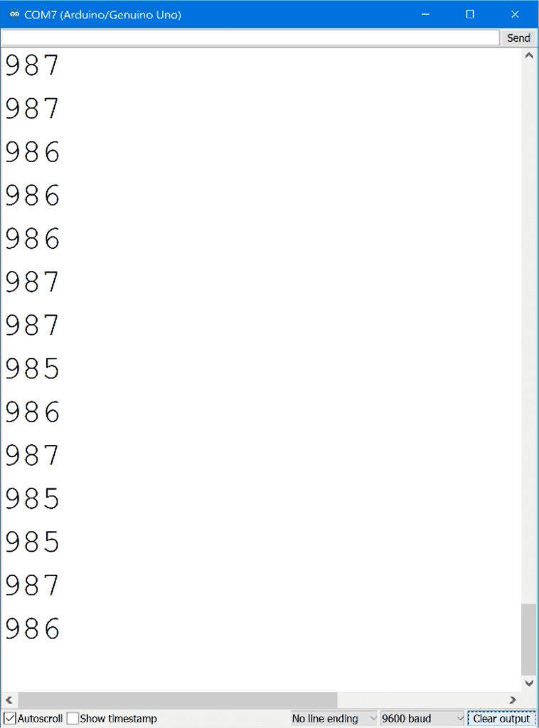
So the sketch will use the analogRead() function to measure the output voltage at the center of the voltage divider, convert it to an integer between 0 and 1023, and print that number to the serial monitor.
Once the circuit is connected and the code is uploaded to the Arduino, place the photoresistor in the dark. The analogRead() values on the serial monitor should decrease. When you place the photoresistor in light, the analogRead() values should increase:
How to Use a Photoresistor to Control Things
Photoresistors are great for making light controlled switches. So now let’s build a light controlled switch that turns on an LED when it’s dark, and turns off the LED in the light.
These are the parts you will need:
Wire up the circuit like this:
Programming a Photoresistor to Control Things
Once the circuit is connected, upload this code to the Arduino:
int photoPin = A0;
int ledPin = 7;

void setup() {
  pinMode(ledPin, OUTPUT);
}

void loop() {
  int lightRaw = analogRead(photoPin);
  int light = map(lightRaw, 1023, 0, 10, 0);

  if (light < 5) {
    digitalWrite(ledPin, HIGH);
  }

  else {
    digitalWrite(ledPin, LOW);
  }
}
Explanation of the Code
We start by declaring a variable for the photoPin, and set it equal to analog pin A0. Then we declare a variable for the ledPin and set it equal to digital pin 7.
In the setup() section, we set the pin mode of the ledPin as an OUTPUT. In the loop() section, we take an analog read of the photoPin, and store the reading in a local variable called lightRaw. To make the raw ADC values from the photoresistor a bit easier to visualize, we use the map() function to convert the values to numbers between zero and ten. The mapped values are stored in a new local variable called light.
The if else statement sets a threshold value that defines when the LED will be switched on and off. When the value stored in light is less than 5, the code in the if statement will be executed. Since we want the LED to turn on when the light drops below the threshold, we digital write the ledPin high.
The else statement is executed when light is not less than 5. So in the else statement we digital write the ledPin low to turn it off.
After you build the circuit and upload the sketch, you should see the LED turn on in the dark, and turn off in the light.
This is a simple example, but it is a functioning light controlled switch. You can switch out the LED with any other device that can be controlled with the 5V signal from the Arduino. Be sure to leave a comment if you have questions about anything!


