If you check out any digital electronic circuit, you’ll mostly find pull-up and pull-down resistors in them. They are used to correctly bias the inputs of digital gates to stop them from floating around randomly when there is no input condition. For any microcontroller in an embedded system such as an Arduino, pull-up and pull-down resistors utilize input and output signals for communication with external hardware devices, the General Purpose Input Output (GPIO). Implementing the pull-up and pull-down resistors in the circuit will let you achieve either ‘high’ or ‘low’ states. If you don’t implement it and there’s nothing connected to your GPIO pins, your program will read a “floating” impedance state.

Pull-up Resistors
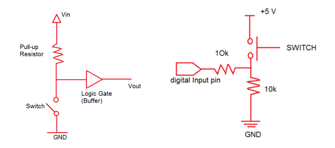
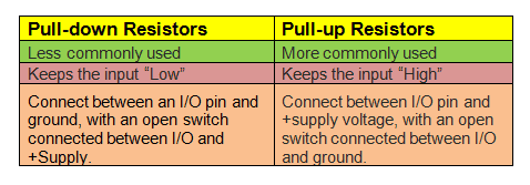
A pull-up resistor is used to establish an additional loop over the critical components while making sure that the voltage is well-defined even when the switch is open. It is used to ensure that a wire is pulled to a high logical level in the absence of an input signal. It is not a special kind of resistor. They are simple fixed-value resistors connected between the voltage supply and the appropriate pin that defines the input or output voltage in the absence of a driving signal. When the switch is open, the voltage of the gate input is pulled up to the level of the input voltage. When the switch is closed, the input voltage at the gate goes directly to the ground. You need to use a pull-up resistor when you have a low default impedance state and wish to pull the signal to ‘high’.
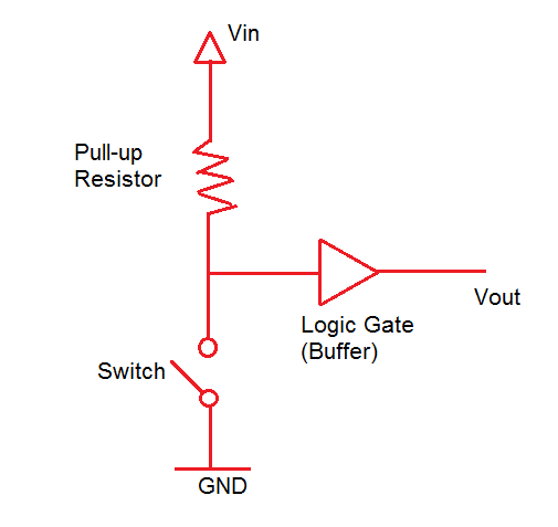
In the figure above, a pull-up resistor with a fixed value was used to connect the voltage supply and a particular pin in the digital logic circuit. The pull-up resistor is paired with a switch to ensure that the voltage between Ground and VCC is actively controlled when the switch is open. At the same time, it will not affect the state of the circuit. If we do not use a pull-up resistor, it will result in a short circuit. This is because the pin cannot be directly shorted to the ground or VCC as this will eventually damage the circuit. Following the principle of Ohm’s law, if there is a pull-up resistance, a small amount of current will flow from the source to the resistors and to the switch before reaching the ground.
Pull-down Resistors
On the other hand, a pull-down resistor is used to ensure that inputs to logic systems settle at expected logic levels whenever external devices are disconnected or of high impedance. It ensures that the wire is at a defined low logic level even when there are no active connections with other devices. The pull-down resistor holds the logic signal near to zero volts (0V) when no other active device is connected. It pulls the input voltage down to the ground to prevent an undefined state at the input. It should have a larger resistance than the impedance of the logic circuit. Otherwise, it will make the input voltage at the pin on constant logical low value no matter the position of the switch. When the switch is open, the voltage of the gate input is pulled down to the level of the ground. When the switch is closed, the input voltage at the gate goes to Vin. Without the resistor, the voltage levels would virtually float between the two voltages.
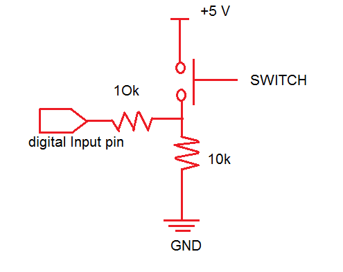
Just like the pull-up resistor in the first figure, the pull-down resistors in this circuit also ensures that the voltage between VCC and a microcontroller pin is actively controlled when the switch is open. Unlike the pull-up resistor, the pull-down resistor pulls the pin to a low value instead of high value. The pull-down resistor which is connected to the ground or 0V sets the digital logic level pin to default or 0 until the switch is pressed and the logic level pin becomes high. Therefore, the small amount of current flows from the 5-V source to the ground using the closed switch and pull-down resistor preventing the logic level pin from getting shorted with the 5-V source.
Ideal Resistance Values for Pull-up and Pull-down Resistors
When the button is pressed, the input pin is pulled low. The value of the resistor near the supply controls how much current you want to flow from VCC through the button, and then to ground. High current will flow through the pull-up resistor if the resistance value is too low. It may cause unnecessary usage of power even when the switch is closed since the device will heat up. This condition is called a strong pull-up and should always be avoided when low power consumption is a requirement.
When the button is not pressed, the input pin is pulled high. The value of the pull-up resistor controls the voltage on the input pin. When the switch is open and a high pull-up resistance value is combined with a large leakage current from the input pin, the input voltage can become insufficient. This is called having a weak pull-up. The pull-up resistor’s actual value depends on the impedance of the input pin that is closely related to the pin’s leakage current.
Based on the two conditions above, for pull-up resistors, you need to use a resistor that is at least 10 times smaller than the value of the input pin impedance. For logic devices that operate at 5V, the typical pull-up resistor value should be between 1-5 kΩ. On the other hand, for switch and resistive sensor applications, the typical pull-up resistor value should be between 1-10 kΩ.
For pull-down resistors, it should always have a larger resistance than the impedance of the logic circuit. Or else, it will pull the voltage down by too much and the input voltage at the pin would remain at a constant logical low value regardless of whether the switch is on or off.
Hope this article has helped you to understand how to use pull-up and pull-down resistors. Be sure to leave a comment below if you have a question!

In the “Pull-up resistors” section you wrote:
“The pull-up resistor is paired with a switch to ensure that the voltage between Ground and VCC is actively controlled when the switch is open.”
Correctly, if the switch is open, is the voltage between the pin and vcc actively regulated, not Ground and Vcc?
Perko Zsolt! Udv nagykanizsarol! a pin es vcc meg a vcc es gnd kozott ugyanaz a fesz, ha jol ertem a kerdest.
I understand the concept that pull-down resistors should always have a larger resistance than the impedance of the logic circuit. But we have a 10K resistor going into the digital input pin (the logic circuit). Assuming there is also some impediance at the digital input pin, wouldn’t the impediance of the digital input pin plus the 10K resistor in front of it be greater than the 10K pull-down resistor? If so, the pull-down resistor ‘will pull the voltage down by too much and the input voltage at the pin would remain at a constant logical low value regardless of whether the switch is on or off.” What am I missing?
When the switch is on the voltage at the node between the two 10K resistors is going to be 5V (ignoring the resistance of the switch). The 10K resistor to ground limits the current through the switch. The 10K resistor in front of the digital input similarly limits the current flow to the input. When the switch is on, the pull down resistor prevents the node from being pulled down by any significant amount. It is only when the switch is open and 5V is removed from the node that the pull-down resistor can pull the node down to ground (logical low value). Hope that helps.