Pulse width modulation (PWM) is a technique used to precisely control analog devices with a digital signal. A pulse width modulation signal consists of electronic pulses that are used to mimic a changing analog voltage.

Pulse width modulation signals are commonly used to control analog devices like servos, LEDs, and DC motors. Projects using these devices need a varying voltage to control the position, brightness, or speed of the device. But most microcontrollers are unable to generate this varying analog voltage. Pulse width modulation is used to simulate this varying analog voltage using a digital microcontroller or timer.
How Pulse Width Modulation Works
You might be thinking, why can’t we just make a varying voltage with a potentiometer or resistor? The answer is that for applications like controlling a DC motor, a large amount of current is needed to power the motor. All of that current flowing through the resistor would quickly burn it out.
In pulse width modulation, a high frequency train of electrical pulses is sent to the device to power it. The pulses can be generated by a drive transistor or power MOSFET.
A pulse width modulation signal occurs in cycles of high and low voltages generated by the transistor. The time it takes for the signal to cycle from low to high is called the cycle duration. The time that the signal stays high is called the pulse width:
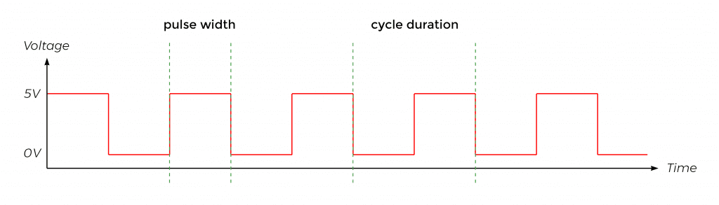
The ratio of the pulse width to the cycle duration is called the “duty cycle”:

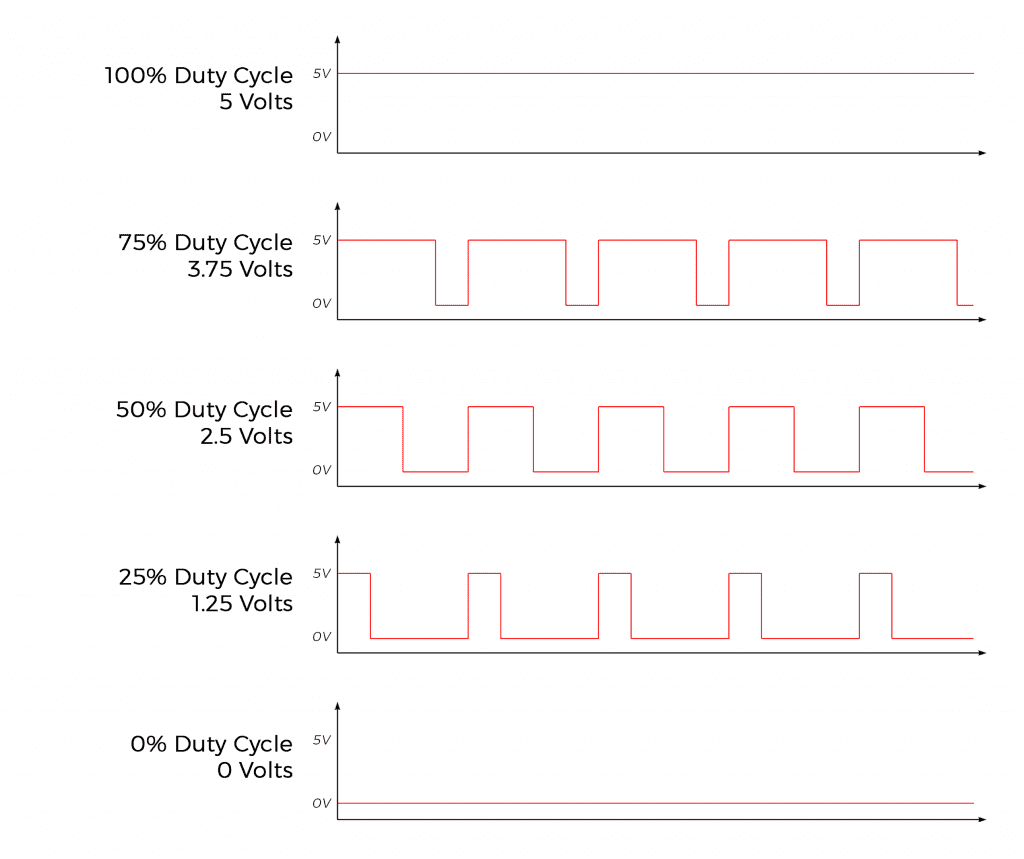
The duty cycle can be used to estimate the apparent analog voltage that a pulse width modulation signal will provide. The diagram below shows the effect of duty cycle on the apparent voltage:
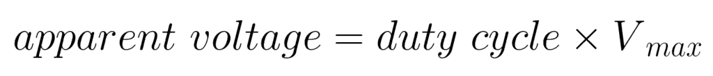
To calculate the duty cycle required for a specific apparent voltage:
For example, in a pulse width modulation cycle with a low time of 13 ms and a high time of 8 ms, the duty cycle is:
8 ms / (8 ms + 13 ms) = 38%
If the pulse voltage (Vmax) is 5V, the apparent voltage will be:
(38%/100%) * 5V = 1.9 volts
Pulse Width Modulation Signal Generator
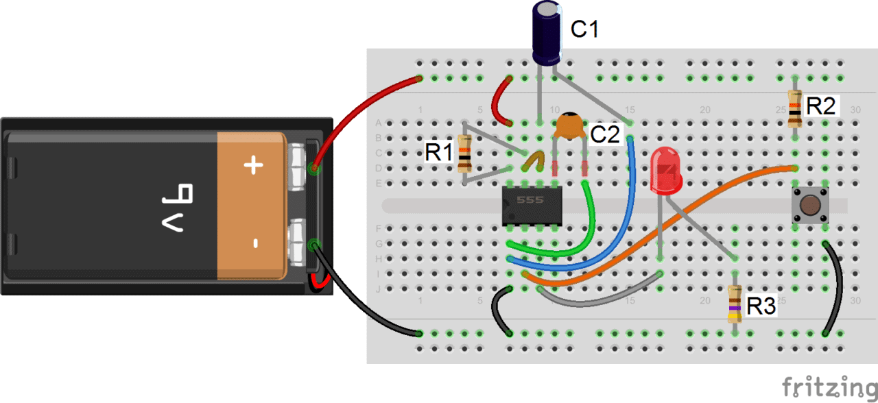
Now that we have the basics out of the way, let’s build a circuit that will generate a pulse width modulation signal by using a 555 timer to switch a power MOSFET transistor.
Here is the schematic:
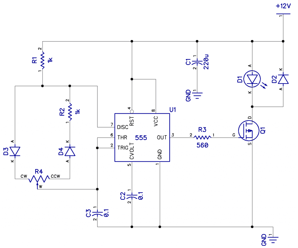
In the circuit above, we see a 555 timer configured as an astable oscillator. The 555 timer will generate the pulse width modulation signal at a specific duty cycle and switch the MOSFET transistor Q1. The MOSFET transistor in this circuit is the IRF540 MOSFET transistor.
D1 is an LED that will be made brighter and dimmer by the PWM signal. But this can be replaced by any other device needing a PWM signal (i.e. DC motors or servos).
Diode D2 prevents any back EMF from an inductive load (created by a motor) from damaging the MOSFET transistor.
The frequency is fixed at about 595 Hz by resistors R1, R2, R4 and capacitor C3.
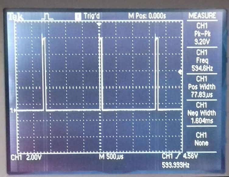
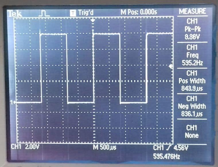
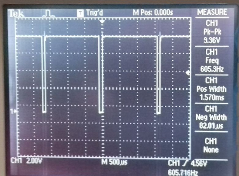
Potentiometer R4 (about 20k) adjusts the duty cycle, and as you can see from the oscilloscope displays below, it can be adjusted from about 78 uS to about 1.6 mS:
A good question to ask at this point would be, given any duty cycle, what effect does frequency have? If the frequency is too low, you will get visible flickering on the LED, and if too high, the control device or the load will not be able to turn on and off fast enough.
We have seen how to build a simple astable oscillator with the 555 timer that generates a pulse width modulation signal to control any any analog device.
Thanks for reading and be sure to leave a comment below if you have any questions!

very clearly explained and very useful to the technical persons specially electronic hobbyist
Hello
The article was very useful.
If you can leave a message about reading data from Logic Analyzer
I need help.
I extracted the information of an RFID tag with Logic Analyzer, but could not read it completely.
You can help.
If you know someone who specializes in this work, help
Grateful.
I am currently working on a college project that involves designing a Pulse Width Modulation (PWM) circuit, and I would greatly appreciate your assistance. Could you kindly provide me with the PCB design and Gerber files for a PWM circuit?
Il nostro servizio permette l’assunzione di persone per lavori pericolosi.
Gli utenti possono selezionare esperti affidabili per lavori una tantum.
Tutti i lavoratori vengono verificati secondo criteri di sicurezza.
assumere un killer
Attraverso il portale è possibile visualizzare profili prima della selezione.
La qualità resta un nostro impegno.
Esplorate le offerte oggi stesso per portare a termine il vostro progetto!
Questo sito rende possibile l’ingaggio di lavoratori per incarichi rischiosi.
Gli interessati possono trovare candidati qualificati per missioni singole.
Ogni candidato sono selezionati con cura.
sonsofanarchy-italia.com
Attraverso il portale è possibile ottenere informazioni dettagliate prima della scelta.
La qualità continua a essere un nostro impegno.
Iniziate la ricerca oggi stesso per affrontare ogni sfida in sicurezza!