A resistive sensor is a transducer or electromechanical device that converts a mechanical change such as displacement into an electrical signal that can be monitored after conditioning. Thermistors, photoresistors, and potentiometers are some examples of common resistive sensors.

Factors Affecting Resistance
The resistance of a material depends on four factors:
- Cross-sectional area or thickness
- Length
- Temperature
- Conductivity
Based on the principle of resistive sensors, the conductor length is directly proportional to the resistance of the conductor and is inversely related to the area of the conductor. L is denominated for conductor length, A for the area of the conductor, and R for the resistance of the conductor. ρ is the resistivity and it is constant for the material used in conductor construction. Thus, it is represented by the equation below:
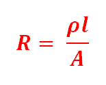
R is the resistance of the conductor, A is the area of the conductor, l is the conductor’s length, and ρ is the resistivity of the conductor.
If you need to change the resistance of a material, you should change the value of the above factors. When the length is modified, the change in resistance is direct. Doubling the material’s length will double the resistance as well. However, if you double the cross-sectional area of the wire, its resistivity will be cut in half. Changing the conductivity and temperature will not affect the resistivity.
Detecting Resistance Changes with Resistive Sensors
Resistive sensors detect changes in resistance. There are different sensors available in the market which consider different factors in detecting resistance.
Examples of some basic resistive sensors:
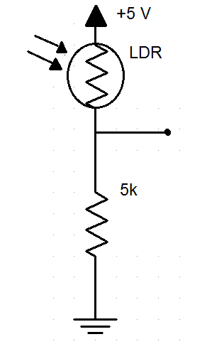
An example of a light-dependent resistor is shown in the schematic above. It consists of a length material whose resistance changes according to the light level. In this example, the brighter the light, the lower the resistance.
We cannot get resistance directly but we can find it by calculating the voltage. The bottom resistance remains constant. The top one is a sensor. The voltage is divided into the resistors going into two directions. Hence, if the resistance changes, the voltage will go up and down. We can detect these changes in resistance using Ohm’s law.
Photoresistors
Also known as Light Dependent Resistors (LDR), photoresistors are light-sensitive devices. They are most often used to indicate the presence or absence of light. In low light, the resistance is very high and drops dramatically when exposed to light. It is made of a high-resistance semiconductor so that when the light of high enough frequency strikes the device, photons absorbed by the semiconductor give bound electrons enough energy to jump into the conduction band. When that happens, the resulting free electron conduct electricity thereby lowering resistance.
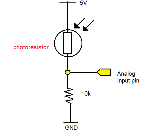
The resistance of a photoresistor decreases as the light incident on the face of the photoresistor increases. By placing the photoresistor in the upper leg of a voltage divider, the output of the voltage divider increases as the light intensity increases.
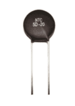
Thermistors
A thermistor is a temperature sensor made up of semiconductor material that executes a large modification in resistance in proportion to a tiny low modification in temperature. It can be used to produce an analog output voltage with variations in ambient temperature referred to as a transducer. This creates a change in its electrical properties due to external and physical changes in heat.
Thermistors are solid-state thermally sensitive transducers with two terminals. They are constructed using sensitive semiconductors based on metal oxides with metalized or sintered connecting leads formed into a ceramic disc or bead. This allows the thermistor to change its resistive value in proportion to small changes in ambient temperature. Its resistance depends on temperature. If the temperature changes, the resistance of the thermistor will be unstable. Thermistors are made up of ceramic and semiconducting materials such as oxides of manganese, nickel, and cobalt.
Types of Thermistors
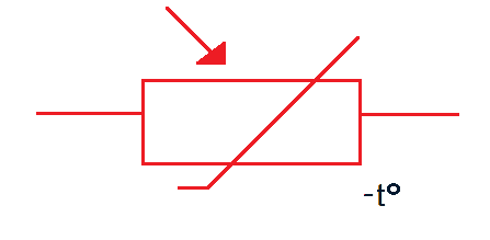
- Negative Temperature Coefficient (NTC) is the most common type of thermistor that has a resistance that falls as the temperature rises. It has a negative electrical resistance versus temperature (R/T) relationship. It means that even small changes in temperature can cause significant changes in their electrical resistance. This makes them ideal for accurate temperature measurement and control.
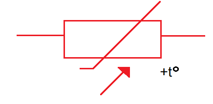
- Positive Temperature Coefficient (PTC) has a resistance that increases with temperature.
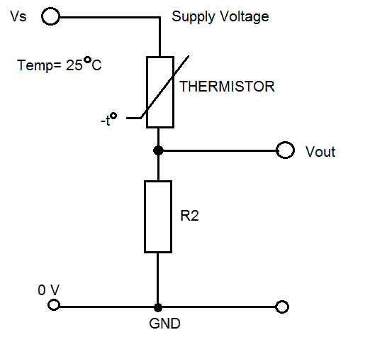
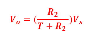
If you measure the voltage output across the fixed resistor R2 in the above example, the thermistor has a rating of 10 kΩ at 25 °C. Let’s say you tried changing the temperature to 100 °C, its resistance will then drop to 674 Ω. Therefore, the voltage output changes when the temperature changes and is given by the standard voltage divider equation below.
Hope this article has given you a better understanding of how resistive sensors work. Just leave a comment below if you have questions about anything!


Wonderful explanation ,looking forward to more…