If you struck a hammer on a thick metal plate and were able to view it in slow motion, you would see it go through several bounces before it settles down and come to rest on the plate. An electrical switch has a set of spring-loaded metallic contacts, and when operated, the contacts close in a manner much like the hammer. High-speed photography captures them repeatedly closing and opening until they settle and close.

This results in false triggering or multiple triggering like a button pressed multiple times. Switch bouncing is not a major problem when dealing with power circuits, but it causes issues on logic or digital circuits. Hence, we use switch debouncing circuits to remove the bouncing from the circuit. The basic idea is to use a capacitor to filter out any quick changes in the switch signal.
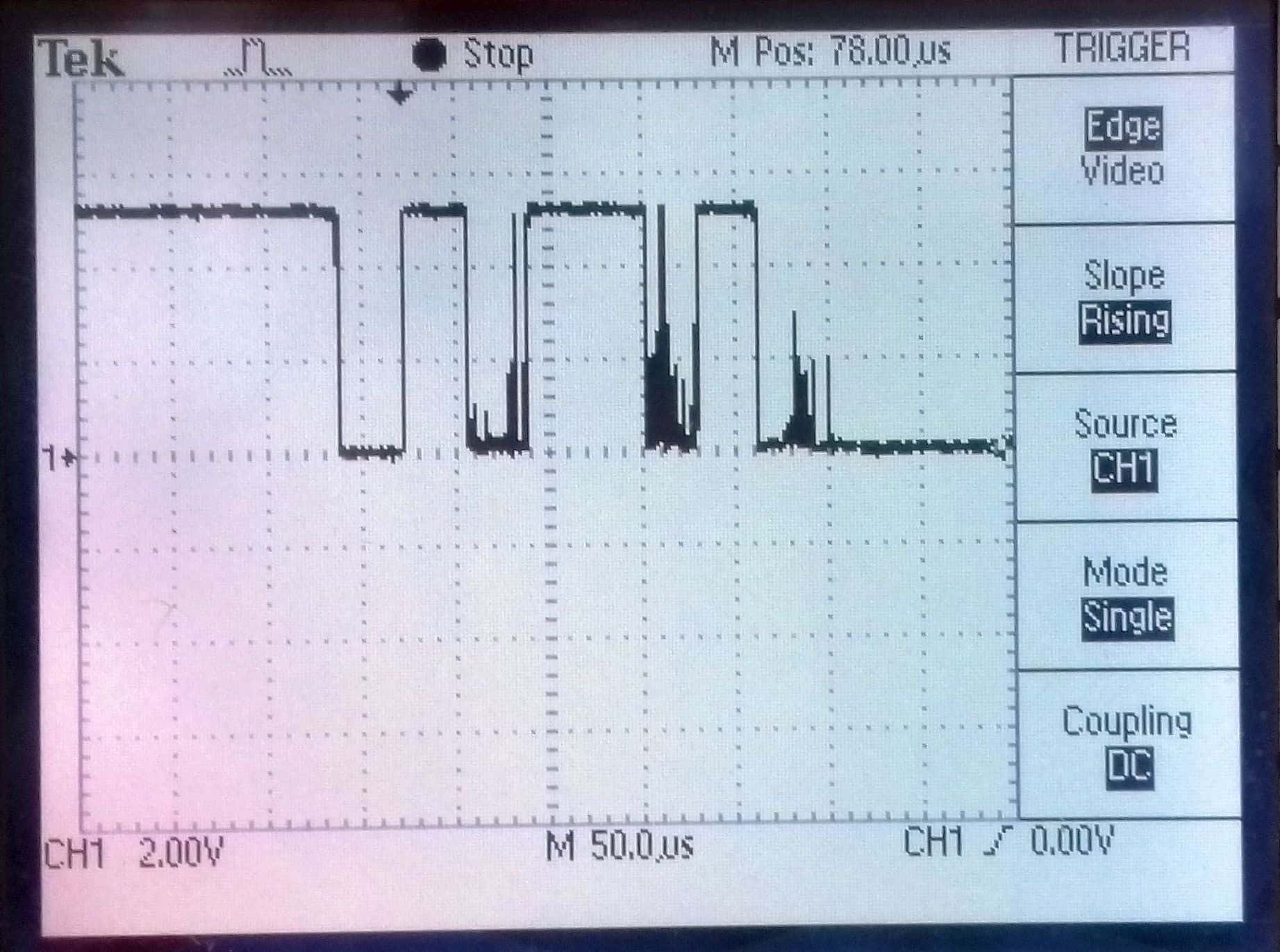
Switch Bounce Oscilloscope Waveform Diagram
If we take the circuit in Figure 1A and connect an oscilloscope probe to J2, set the scope to a single trigger, then press the button, you will get something like Figure 2 (below). Both are from the same switch pressed at different times. The scope time-base is 50uS per division, so you can see the contacts bounce up and down during the first 250 or so microseconds. In an analog circuit, this would be of no concern. But a microprocessor running at 16 million cycles per second will see this as someone pressing the switch multiple times. And if this were part of some counting type program, you would get the wrong number of presses.
Switch Debounce Oscilloscope Waveform Diagram
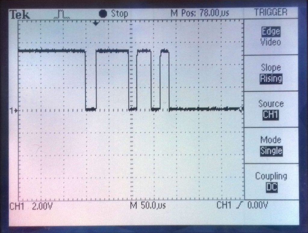
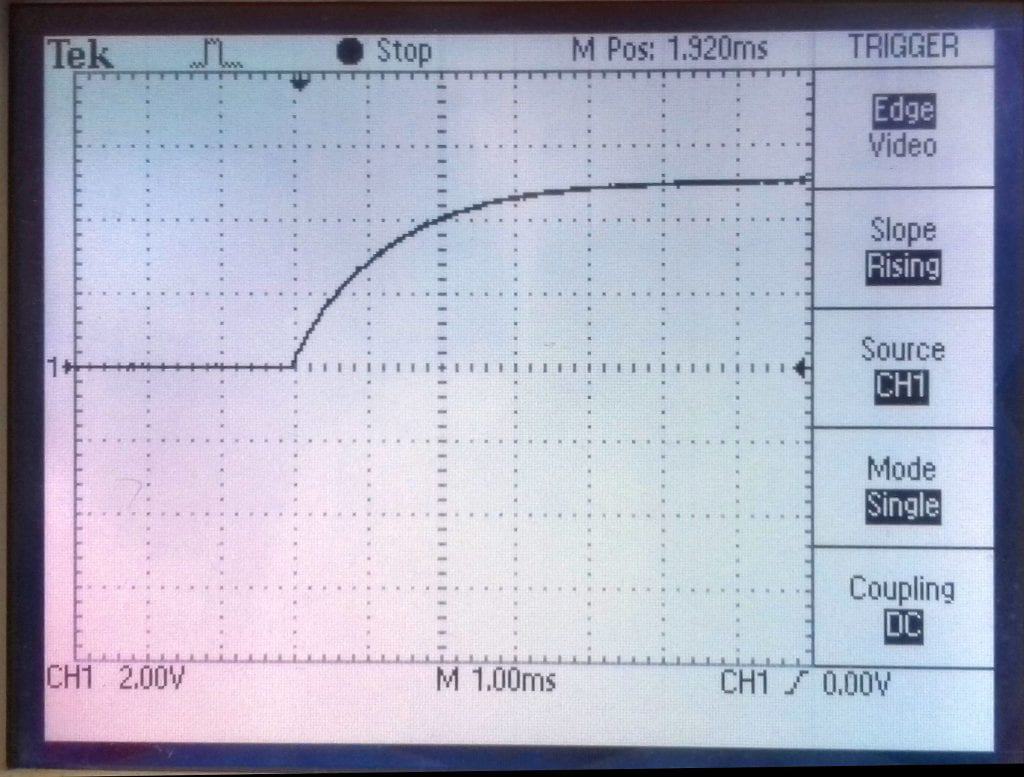
In Figure 1B above, we added a small ceramic capacitor with a value chosen such that the time constant of R3/C3 is longer than 250uS. A 0.1uF will give a time constant of 1mS, or five times longer. Figure 3A below shows the result of adding the 0.1uF capacitor.
In Figure 1C and D above, we see much-improved circuits using a Schmitt trigger. Schmitt invented this circuit way back in 1937. He used a comparator with positive feedback. It has only two stable states—fully on or fully off—but unlike a comparator without positive feedback, it has hysteresis. This means there is no “hair trigger” spot in the center of the range where the comparator will flip on or off. Instead, if you flipped it on, you must come back well past the trigger point to flip it off again, making it great for dealing with all those undecided bouncing states.
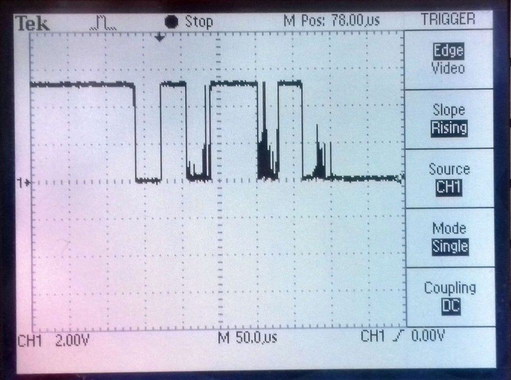
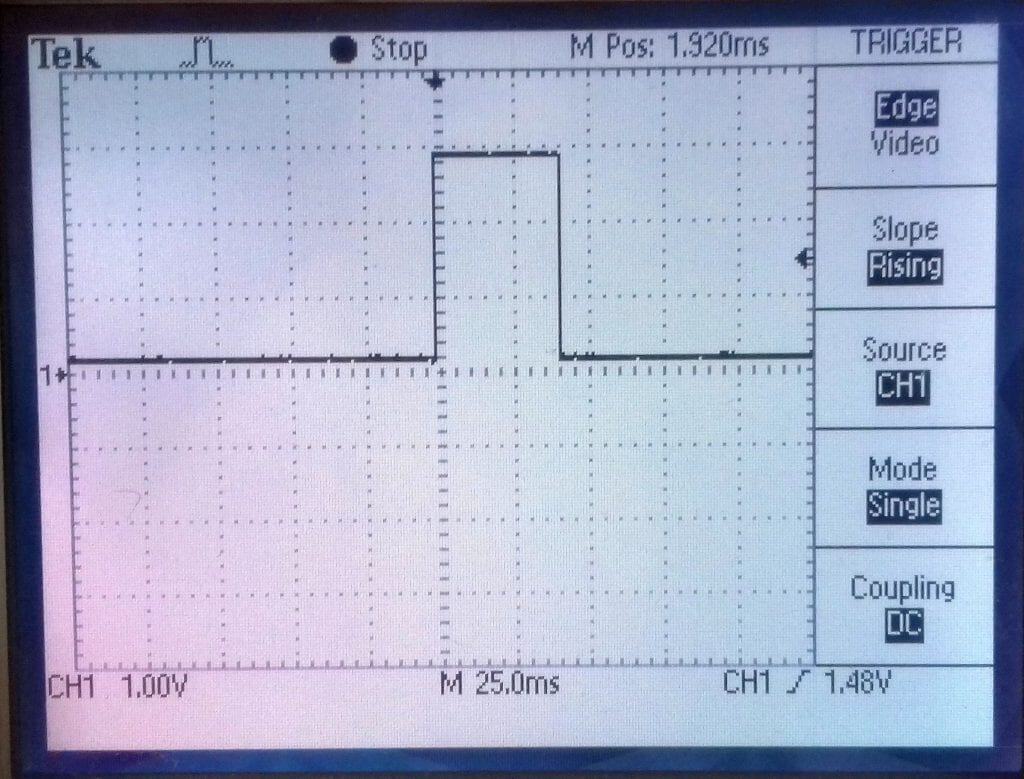
Figure 3A above shows the result of the simple capacitor debouncer in 1C. It would work fine for circuits that are not timing-critical. But what is the purpose of R6 here? It actually has nothing to do with the debouncing. When C3 gets rapidly discharged (shorted, in fact), it may well create switching transients of its own by causing large, rapid currents in the wiring. R6 slows the discharge down a bit to overcome this noise. R6 is 1/10 of R3. Figure 3B (below) shows the vastly improved clean switching of either Schmitt circuits in Figures 1C and D.
But how about D1? It enables C2 to charge faster without affecting the discharge path of R7. Since the Schmitt trigger is an inverter, it reverses the output.
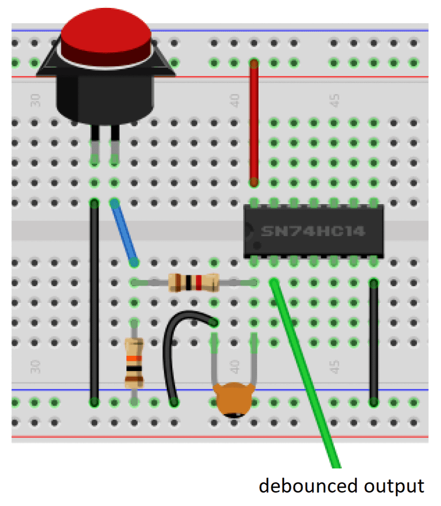
Debouncing a Switch With an SN74HC14 Schmitt Trigger
The wiring diagram below shows how to add an SN74HC14 Schmitt trigger to the circuit in Figure 1C. In a real circuit, any unused CMOS inputs should be grounded to prevent unwanted effects. In this diagram, they were left out to not complicate the drawing.
These are the parts you will need to build this project:
- Jumper wires
- Breadboard
- SN74HC14N Schmitt trigger
- Tactile push button
- 1K and 10K Ohm resistors
- 0.1 uF ceramic capacitor
Once you have all of the parts, connect the circuit following this wiring diagram:
In hardware applications, these debouncing circuits are necessary. However, in many Arduino programs, you will be able to debounce a switch in software. There is no harm in doing both as this will also reduce unwanted noise and transients, possibly affecting other parts of your circuit.
Let us know in the comments how this works for you!

I use this function to perform the Schmidt Trigger operation in Arduino:
/********************************************************
function to read analog pins as debounced digital inputs
works with 10k pull up and 0.01 or 0.1 ufd cap across switch
has 33 percent hysteresis.
Beware this will spin forever on an unterminated analog input
********************************************************/
boolean Button(int Bpin) {
// Force an initial analogRead
int level = 600; // middle of dead zone
while (level > 400 && level = 800) {
return HIGH; // in upper third
}
else {
return LOW; // in lower third
}
}
On the breadboard diagram, the 10k resistor is shown connected to ground. But that’s a mistake: In the schematic it’s connected to +5v.
Hi Jon,
This is great and worked perfectly for a circuit I have built using six push buttons and interrupts on an ESP32.
Regards,
Christopher
Hey Christopher,
in your circuit, have you connected the 10k resistor to +5v as shown in the schematic or to GND as shown in the breadboard diagram? I am planning to replicate this circuit and I am a bit unsure now after reading Jon’s comment and seeing that it is indeed different between schematic and diagram.
Would love to hear from you or Graham.
Thanks,
Julian
Hi Julian,
Please follow Grahams schematic options, as they are accurate. You will note on his four options, each of the 10k resistors are all connected to +5V, as the switch takes the level low.
Sorry I meant Graham