A DC motor is a device that converts electrical energy into mechanical energy. Today, you find DC motors in many devices we rely on every day such as home and office appliances, automobiles, access control systems, and toys. In this tutorial, we will cover the basic principles of DC motors and show you how to control the speed of a motor using PWM, an H-bridge circuit, and the L293D motor driver.

How DC Motors Work
A current carrying wire in the presence of a magnetic field experiences a mechanical force that acts in a particular direction.
To determine the focus of this force, Sir John Ambrose Fleming established a simple way that uses one’s left hand to visualize the relationship between the flow of current, the direction of the magnetic field, and the direction of the force. This simple yet highly effective technique became known as the Fleming Left-hand rule.
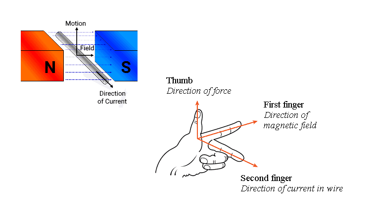
In a DC motor, a shaft is connected to a wire coil that has current running through it. There are also circular magnets surrounding the wire coil. When the motor is supplied power, the current flows through the wire coil, and the magnetic field causes the coil to rotate and turn the shaft.
Properties of DC Motors
When selecting a DC motor, you need to consider several characteristics that specify the electrical properties of the motor. This includes:
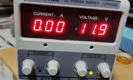
- Voltage: You can find DC motors that operate from as few as 1.5V all the way up to 100V.
- Torque: Torque is the amount of rotational force that a motor produces (in Newton-meters). DC motors for hobby projects can range from as low as 2.8 g-cm to as high as 58 kg-cm.
- Starting torque: The maximum torque a motor produces to begin the rotational movement of the load. DC motors have a high starting torque.
- Motor speed: The rate of motor rotation in revolutions per minute (RPM). Typical no-load speeds for DC motors range from 1-20,000 RPM.
How to Control Motor Speed with PWM
The speed of a DC motor is directly proportional to the supply voltage. A simple way to control the speed of a DC motor is to regulate the supply voltage with pulse width modulation (PWM).
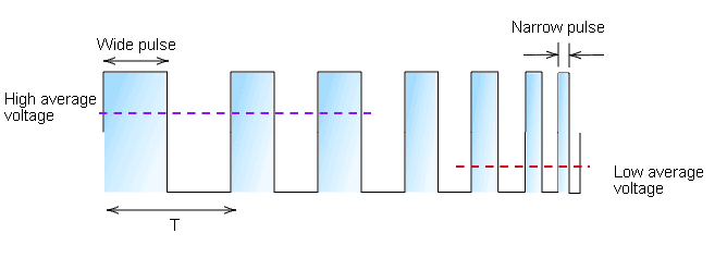
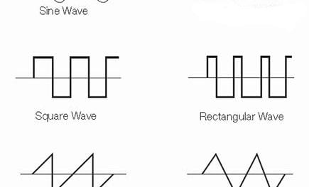
The basic idea behind PWM is that it switches the supply voltage ON and OFF very quickly. By adjusting the length of the ON/OFF pulses, we can set the voltage to anywhere between 0V and the maximum voltage. We will use this PWM signal to power the motor directly.
PWM Motor Driver
There are several ways to generate the PWM signal for the motor, but in this tutorial we will use the 555 timer. Here’s a schematic of the circuit:
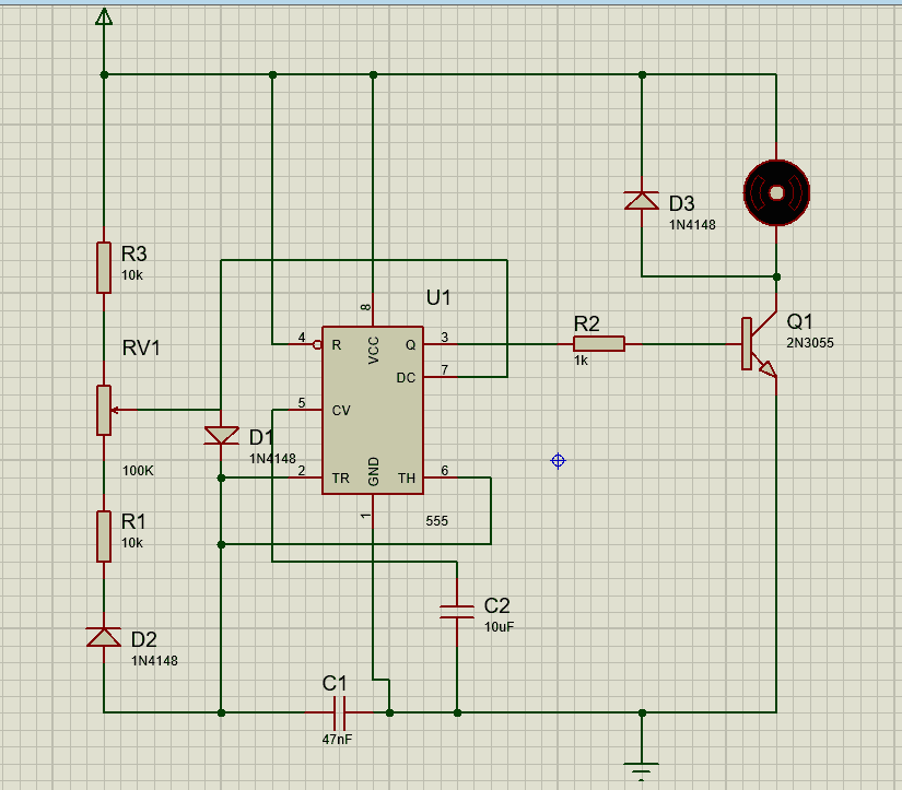
The output of the 555 timer switches transistor Q1 on and off. The capacitor C1 charges and discharges through the resistors R1 and R3. The time to charge or discharge the capacitor depends on the values of R1 and R3. As soon as the capacitor charges, it quickly discharges through diode D2 and the variable resistor RV1 into pin 7. During the discharging process, the output of the 555 timer drops to 0V and switches “OFF” the transistor. Turning the variable resistor adjusts the speed of the motor.
H-Bridge Motor Driver
A typical DC motor has two connecting leads – one for the negative terminal and the other for the positive terminal. If you reverse these terminals (changing the polarity), the motor will spin in the opposite direction. Of course, there are better ways of controlling the direction of the DC motor without constantly changing the terminals.
We can use an H-Bridge circuit to do this. The H-Bridge circuit derives its name from the four transistors that look like an “H.” The H-bridge circuit achieves motor control in both directions by using different combinations of the switches (S1-S4). In a real-life scenario, we use transistors instead of basic switches.
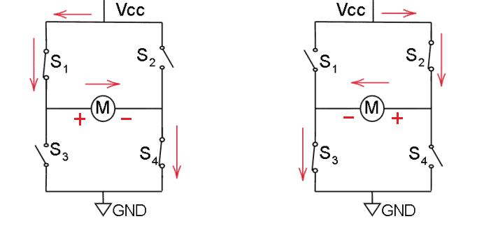
The working principle of this circuit is simple. We have four switches, S1-S4. If we open S2 and S3 and close S1 and S4, the current flows clockwise from VCC to the Ground. Now, to reverse the polarity of the motor, we open S1 and S4 and close S2 and S3. Now, the DC motor runs in the opposite direction.
Here’s the schematic for an H-Bridge motor direction control circuit:
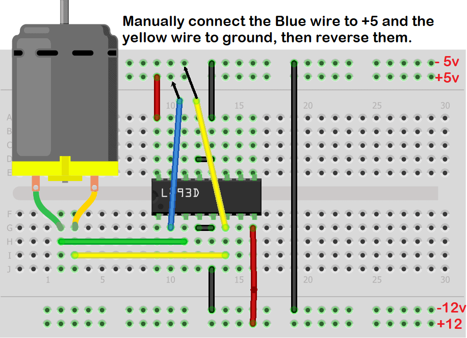
L293D Motor Driver
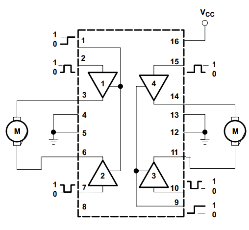
As the name suggests, the purpose of the L293D motor driver is to drive DC motors. The L293D is a popular motor driver IC that has a built-in H-bridge circuit that can drive two DC motors simultaneously. It can supply up to 1A of current and voltages from 4.5V to 36V.
This means the L293D motor driver is ideal for building multi-wheel robot platforms. Here’s a diagram of the L293D showing how to connect the motors:
L293D Pin Descriptions
| L293D Pin | Description |
| 1 (Enable 1-2) | Controls the left part of the driver |
| 2 (Input-1) | Signal input pin |
| 3 (Output-1) | Connects to one of the motor terminals |
| 4 & 5 | Ground |
| 6 (Output-2) | Connects to one of the motor terminals |
| 7 (Input-2) | Signal input pin |
| 8 (Vcc2) | Motor supply voltage: will need to be greater than 4.5V |
| 9 (Enable3-4) | Controls the right part of the driver |
| 10 (Input-3) | Signal input pin |
| 11 (Output-3) | Connects to one of the terminals of the motor |
| 12 & 13 | Ground |
| 14 (Output-4) | Connects to one of the terminals of the motor |
| 15 (Input-4) | Signal input pin |
| 16 Vss | Power source |
Hope this article has helped you to better understand how to incorporate DC motors into your electronics projects! Leave a comment below if you have any questions.


What are the key properties to consider when selecting a DC motor for a project?