
Servos are used for a wide range of applications, from simple electronics projects, to robots, industrial equipment, and even automated manufacturing systems. Servos are DC or AC motors that can rotate to a specific position and hold that position indefinitely. They are also referred to as rotary actuators, since they allow for precise control of angular positions.

There are two types of servo motors – AC and DC. An AC servo can handle higher currents, so they’re typically used in industrial machinery. DC servos are not designed for high currents, so they are usually used for low power applications.
How Servos Work
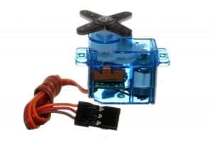
Inside a servo, there is typically a small DC motor, a potentiometer, and a control circuit. As the motor rotates, the potentiometer’s resistance changes, and with this, the control circuit can precisely regulate the movement. The servo circuitry is built right inside the motor unit and has a positionable shaft, usually fitted with a gear and a control arm.
Using a potentiometer attached to the rotating shaft, servos sense position. The incoming pulse is measured, which then applies current to the motor to turn the shaft until the potentiometer indicates that the position corresponds to the incoming pulse width. This is a form of feedback control. During this time, the motor receives the desired position from the pulse width, and the actual shaft position is fed back to the circuit via the potentiometer. A servo is a device that uses feedback to achieve the desired result. Most servo motors have a rotational range of 0-180 degrees and provide a location/angle feedback loop. We can actually program a servo to go to a specified position using an Arduino.
Feedback Potentiometer
Feedback actuator and potentiometer make up the phrase feedback potentiometer. A feedback actuator is a type of linear actuator that incorporates positional feedback. It is adaptable to applications where a closed-loop system is needed. But what is a potentiometer used for? The potentiometer is used to read the position of an actuator as it cycles.
The benefit of using a potentiometer feedback system in a linear actuator is that the controller doesn’t have to keep the state or remember where the actuator shaft is. The potentiometer offers an absolute position any time the controller reads the sensor, though that reading may not reflect the linear actuator shaft’s actual position.
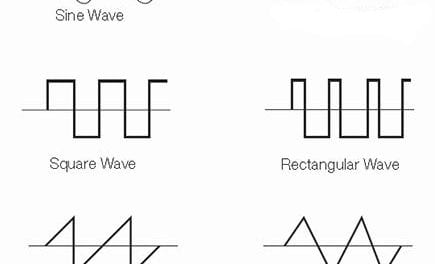
Pulse Width Modulation (PWM)
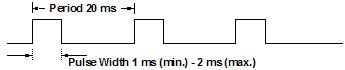
Pulse width modulation is a type of digital signal. PWM is used in a variety of applications, including controlling servo movement or position. It is a method of reducing the average power delivered by an electrical signal. Pulse width modulation is a type of digital signal. PWM is used in a variety of applications, and that includes controlling servo movement or position. It is a method of reducing the average power delivered by an electrical signal.
Going to servo movement or position, or servo control— this is done by sending a servo a pulse width modulation (PWM) signal. This signal is a series of repeating pulses that determine the position to be achieved by the servo. The PWM signal comes from common microcontrollers such as Arduino, and it could also come from a radio control receiver. The electronics inside the servo translate the width of the pulse into a position. When the servo is commanded to rotate, the motor is powered until the potentiometer reaches the value corresponding to the commanded position. Given the rotation constraints of the servo, neutral is defined to be the center of rotation. A servo motor can usually only turn 90° in either direction for a total of 180° movement. The PWM sent to the motor determines the position of the shaft, and based on the duration of the pulse sent via the control wire; the rotor will then turn to the desired position.
Servo Pins/Wires
Usually, servos have three wires. These are for the power, the ground, and the signal. Typically, the power wire is red, which should be connected to the Arduino board’s 5V pin. The ground wire is typically black, which should be connected to the ground pin on the Arduino board. Lastly, the signal wire is typically yellow, orange, or white. The signal wire is then connected to a digital pin on the Arduino board. Remember to plug these wires correctly.
How to Control Servo Position
By pulse width modulation (PWM), servos are controlled through the control wire. A servo motor can usually only turn 90° in either direction for a total of 180° movement. The motor’s neutral position is defined as the servo position with the same amount of potential rotation in both the clockwise or counter-clockwise direction. It is often called the center. The PWM signal sent to the motor determines the shaft’s position and is based on the duration of the pulse transmitted through the control wire. It will then be turned to the desired position.
When these servos are commanded to move, they will move to that position and hold that it. If an external force pushes against the servo while the servo is holding a position, the servo will resist moving out of that position. The maximum amount of force the servo can exert is called the torque rating. Servos will not hold their position forever, though; the position pulse must be repeated to instruct the servo to stay in that position.
All servos rotate clockwise and counterclockwise. The direction the servo rotates depends on the signal the servo is receiving.
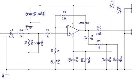
Sample Schematic for a PWM Servo Control Circuit
These are the parts you will need to build this servo control circuit:
- 555 Timer
- 1N4148 diode
- Four AA batteries
- Battery holder
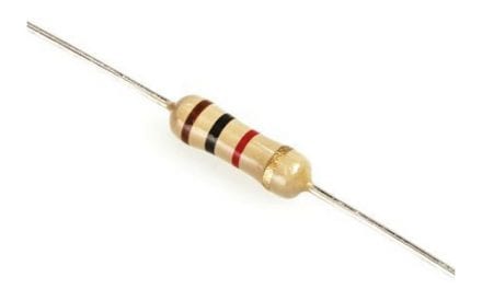
- 10K, 240K Ohm resistors
- 10 nF, 120 nF capacitors
- 50K potentiometer
- Jumper wires
- Breadboard
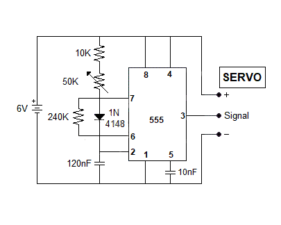
When you turn the potentiometer knob, the servo should turn appropriately. Thanks for reading! Be sure to leave a comment below if you have any questions.


