In a previous article, we looked at the design of transistor amplifiers. Here, we are going to put together the building blocks of an IC-based audio amplifier. This is simpler than a transistor amplifier in some ways, but harder in others as the very high gain available can lead to nasty feedback effects.

Choice of an Amplifier Chip
There are many amplifier chips choose from, and we will look at a few of them. But first, we need to understand their specifications to make the best choice. These requirements apply equally to small op-amp amplifiers and the next expensive Hi-Fi stereo you want to buy.
- Power output
- Frequency response
- Input impedance
- Output impedance
- Noise performance
- Distortion
- Power supply requirements
The main question in choosing an amplifier is how powerful you need it to be. Will it be a headphone amplifier, a PA system, or a guitar amplifier?
Here are three common and widely used amplifiers with different power ranges:
| Specification | LM386 | LM1875 | LM3886 |
| Supply voltage | 12V | 60V | 80V |
| Output power | 0.5W | 25W | 60W |
| THD | 0.2% | <0.6% | 0.03% |
| Noise i/p V | Not spec | 3uV | 2uV |
| Gain bandwidth prod | 300kHz | 5.5MHz | 8MHz |
Characteristics of a Good Audio Amplifier
Power Output
The first design criterion is power output. The most expensive part of an amplifier is the power supply transformer. Different amplifier chips have different power requirements, so consider your design goals and budget before deciding on a particular output power.
A 20W amplifier is not very much louder than a 10W amplifier; only 3dB, and that’s about the smallest change your ear will detect. A 10W amplifier is not 10 times louder than a 1W amplifier; only twice as loud. The more important aspect is the dynamic range.
Let’s say you had a CD player with a dynamic range of 60dB. This means that if the smallest soft sound you wanted to reproduce were at a level of 1mW, the amplifier would need to reproduce the loudest one at a thousand Watts!
Input and Output Impedances
The output impedance is not actually that much of a concern. Most amplifier chips are designed to load into 8Ω speakers and often much less, provided you don’t exceed the total device dissipation.
If you want to measure your amplifier’s output impedance, apply a sine wave to the input at about ¼ power level and load the output with suitable size resistors until you find the value that drops the loaded value to half the unloaded value—that resistor is equal to the output impedance.
The input impedance is more important. If it is too high, you may run into noise or radio interference, and if it is too low, you will load the source. Most amplifiers are best designed to match a Hi-Fi standard of 47kΩ, but this is not the best if you design for the lowest noise. Professional mixers and PA systems are designed for low impedance (600Ω) microphones, giving them better noise performance.
Frequency Response and Power Bandwidth
An audio amplifier must reproduce signals from 20Hz to 20kHz (although very few people except children can hear the entire range). So frequency response is usually taken to mean the amplifier must deliver its rated power output across this range with no more than a 3dB drop in level.
On the other hand, power bandwidth tells us what frequency response the amplifier can achieve given a desired gain or amplification. The LM386, for example, with a gain-bandwidth product of 300kHz, can only give a gain of 30 at 10kHz or 10 at 30kHz. The other two amplifiers are vastly superior, and the LM3886 with a value of 8MHz should give a gain of 8000/20 at 20kHz or 400 times.
But why would you want to do this? If you applied huge amounts of negative feedback, you would reduce the THD to ridiculously low levels—0.03% as in the data. The fact is, no one can hear this, not even 1%, and what you will achieve is abysmal TID (Transient Intermodulation Distortion) and phase shift distortion, something amplifier developers and Hi-Fi sales brochures are very careful to ignore.
Distortion
THD or Total Harmonic Distortion is not such a bad thing, and anything less than 0.5% is fine. In fact, your own ear is producing more than 0.5% THD inside your head anyway. Clipping distortion is a bad thing when the amplifier clips (the signal has reached the supply rail levels), the signal is going square and is thus full of harmonics. Most speaker systems are rated at their power level to expect 75% of the energy to be below 250Hz.
This is not the case with clipping; there could now be 75% in the expensive tweeter’s frequency range, and they are now severely overdriven and sure to die soon. Crossover distortion is not something to expect in this kind of amplifier. Here is an article on TID distortion and phase accurate amplifiers to help explain more.
Noise Performance
Any noise in the power supply will appear in the amplifier output, so it goes without saying that the power supply unit (PSU) should either be well regulated or have very substantial decoupling capacitors to eliminate ripple. Large decoupling caps will also prevent low frequency oscillating (or ‘motor-boating’) in the amplifier.
Amplifiers are also vulnerable to strong RF signals picked up on the input wires, so it is important to tailor the amplifier’s frequency response to only what you can hear. The remaining noise is a function of what is happening at the input impedance.
Noise occurs in all electronic circuitry. The main types are:
- Thermal noise
- Shot noise
- Flicker (1/f) noise
- Burst noise
- Avalanche noise
The only one we are concerned with is thermal noise, since it is the only one we can control and is the worst offender. Thermal noise is a linear function of an equivalent resistor representing the amplifier’s input impedance. It increases ten times for each 100 times increase in resistance, so the input impedance should be kept as low as possible. There is an excellent article on noise here.
Feedback and Grounding Issues
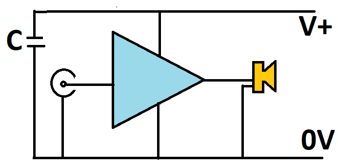
The schematic below shows a simple amplifier schematic. As with all schematics, no attempt to show wiring layout has been made and there is no indication of any issues:
The schematic below shows the danger. The red blocks are the ever-present complex impedances in the wiring and PCB tracks:
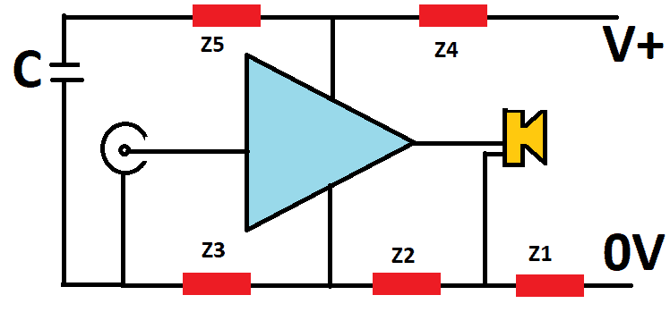
These are both resistive and inductive. The resistive part is constant with rising frequency, but the inductive part is not and soon takes over in magnitude as the frequency rises. Any current drawn through these impedances will cause a voltage to appear across them.
Imagine every time the speaker needs to draw a bite of current; it will cause a volt drop across Z1, effectively in series with the rest of the amplifier. Likewise, as the amplifier demands a current, it will cause a volt drop across both Z2 and Z3. Finally, any attempt by C to charge will do the same through Z4 and Z5 and insert this volt difference to the input of the amplifier, which will now oscillate.
The schematic below shows how to overcome all these problems:
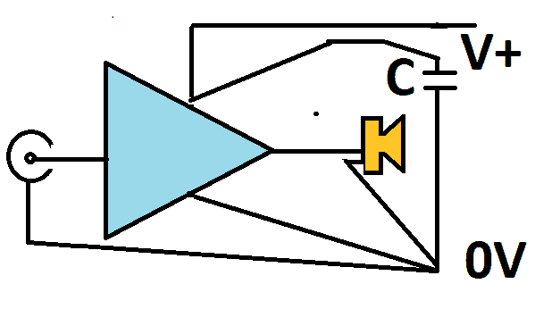
Everything has its ground connection brought to one point, and this is usually the point where the main smoothing/reservoir capacitor goes to the ground. Note that we are not talking about noise or mains earthing here; just oscillating and feedback. In many cases, the reservoir capacitor is going to be quite large—at least 1000uF. In the same way, to prevent a volt drop from being inserted into the +ve supply line, the +ve end of the cap should be as close to the amplifier +ve pin as possible.
How to Build an LM1875 Audio Amplifier
We are going to design and build an amplifier based on the LM1875 amplifier chip. Here’s a pin diagram of the LM1875:
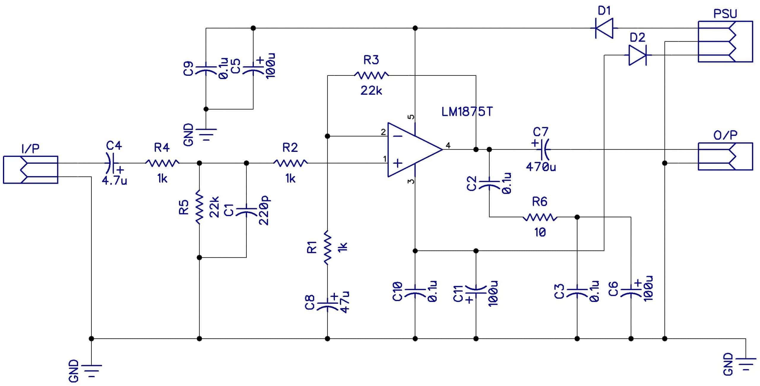
The circuit is fairly simple. It’s the same schematic included in the LM1875 datasheet:
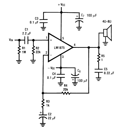
I changed a few things and used the following design which works very well and is very stable:
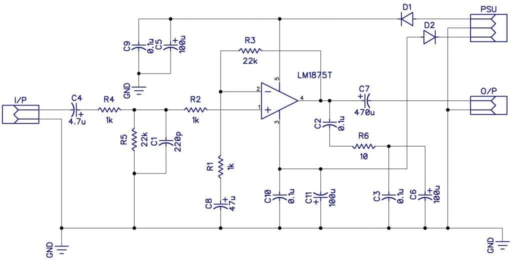
The gain is set at 22X by the ratio of the resistances of R3/R1.
I added C1 to make an upper-frequency cut-off filter at about 30kHz. C4 and R4 control the lower frequency cut-off.
C2 and R6 are added to provide a constant output impedance at frequencies above the range to prevent oscillation (R6 only starts working when the output is about 150kHz).
Placing a potentiometer at the input before C4 will make a volume control dial.
D1 and D2 are just reverse connection protection diodes.
The circuit above shows a dual power supply that can supply -25V/0V/+25V. If a dual supply is used, C7 can be omitted and the output connected straight to the speaker. The voltage must never exceed 30V.
These are very rewarding amplifiers to build! If you obey the grounding rules, they are almost guaranteed to work the first time and provide a very clean listening experience. The LM386 makes a great headphone, intercom, or radio amplifier, and the LM1875 and LM3886 make great Hi-Fi or guitar amplifiers.
To learn more about building amplifiers with the LM386 check out our article on how to build a great sounding audio amplifier with the LM386.
To learn more about building amplifiers with the LM3886 Hi-Fi amplifier, check out our complete guide to design and build a Hi-Fi audio amplifier with the LM3886.
Thanks for reading! Leave a comment below if you have questions about anything!


Why “The voltage must never exceed 30V.”?
Isn’t the limit is 2x25V?