A power inverter is a device that can convert a DC power supply (typically from a battery), into a high voltage (110V-220V) AC current.

Power inverters are typically used to create a mains power backup from a set of 12V batteries in the event of a power outage. They are also used in systems where the mains power is supplied by solar panels or wind generators. Power inverters are also an important part of un-interrupted power supplies.
How Power Inverters Work
Power inverters range from simple DIY circuits using a few transistors and a transformer, to expensive commercial units using microcontrollers to generate PWM sine waves.
It’s important to calculate the current that can be supplied by a power inverter. Otherwise the power inverter might not be able to supply enough current to power your devices. To do this, find the power inverter’s VA rating and voltage rating. As an example, if the power inverter’s output were rated at 100VA and 110V, the output current would be 100VA / 110V = 0.9A.
A WORD OF CAUTION: This project will involve working with high voltages. This project should only be built if you are trained to work with high voltage electronics. Failure to do so could result in fire, injury, or even death.
How to Build a Power Inverter
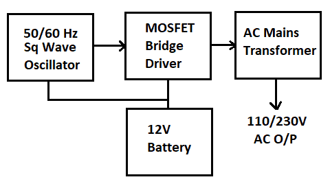
We are going to build a power inverter that takes its input power from a 12V battery, and outputs a 110V/230V AC current. The circuit is outlined in the block diagram below.
Here is the circuit schematic:
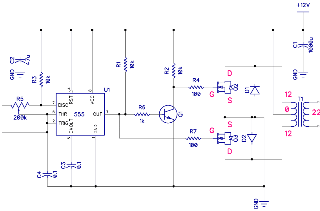
The 50Hz oscillator is provided by the 555 timer. Transistor Q1 is an inverting transistor to give a 180º phase shift. The frequency is controlled by potentiometer R5. It can be set to 50Hz or 60Hz.
A half-bridge MOSFET circuit is connected to the output of the 555 timer. The MOSFET transistors are switched on and off by the square wave generated by the 555 timer.
I found that the MOSFETs need to be low Rds types such as the IRF540 MOSFET transistor or IRLZ44 MOSFET transistor. These will also need a heat sink.
The drains of the MOSFET transistors are connected to the +12V and -12V sides of mains transformer T1. Since T1 is an inductive load, we need to have two flyback diodes (D1 and D2) to prevent a back EMF spikes from killing the MOSFET transistors.
The size of the mains transformer and the amount of current that can be drawn from the battery will govern how much AC power is available. But in general, if you have a 100VA, 110V transformer, then you should be able to get close to 100VA / 110V = 0.9A. It’s only close because the transformer’s efficiency will probably be around 70%, so in reality the output current will be closer to about 0.63A.
When I built this circuit, I used a 12V battery providing 4.5A of current. The power inverter produced about 190V AC, which was enough to power a 60W incandescent lightbulb fairly brightly.
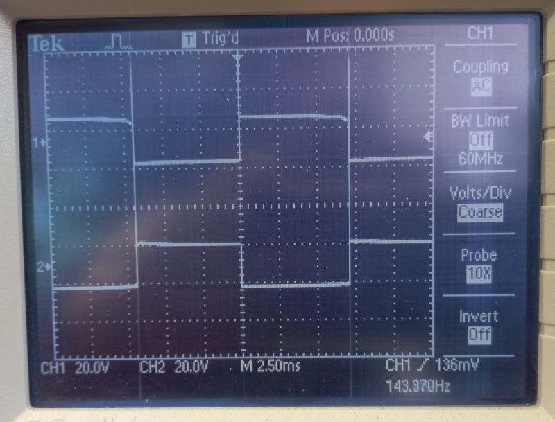
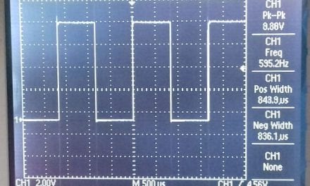
To analyze the circuit in more detail, I connected the gates of the MOSFETs to an oscilloscope to compare the waveforms at the output and input of the MOSFET circuit. Note that they are 180º out of phase:
This power inverter circuit worked quite nicely. Be sure to leave a comment below if you have questions about anything!


Hi,
I would like to know if we change the “555” part with a sinusoidal generator, the inverter will also work? Will it deliver a sinusoidal 220 Volt output in this case?
Many thanks.
Lahcene Akrour
short answer: no
the mosfet need a sharp wave, full open or full closed.
between this, the mosfet is ‘only’ a resistor and heats up – this ‘time in the middle’ must reduced to a minimum.
if you want sinusoidal, you must generate variable output voltage with a higher frequence, so you can between the steps higher the voltage to rise, lower then to fall to zero, lower to fall to -12, rice to zero, rise to +12 and so on.
Thanks for explaining power inverters. A power inverter is a tool to convert DC power to AC power. We need AC power to run all those devices that require AC power. However, there are many DC devices that can be connected with a 12V battery, in this case, you may not need a power inverter.
Can you help me, please?
I wish to build a very simple, very small inverter.
18VDC input @4A peak -to- 18VAC output @ 4A peak.
18VDC power source: suitable LiPo battery.
Could your design/components be modified accordingly?
Thank you.