A multiplexer is best defined as a combinational logic circuit that acts as a switcher for multiple inputs to a single common output line. Also known as “MUX” or “MPX”, it delivers either digital or analog signals at a higher speed on a single line and in one shared device but then recovers the separate signals at the receiving end. An MUX has a maximum of 2ⁿ (two raised to n) data inputs. One of the inputs is connected to the output based on the value of the selection lines. There will be 2ⁿ possible combinations of 1s and 0s since there are ‘n’ selection lines.


Multiplexing is a technique of transmitting multiple signals over a single medium. There are different types of multiplexing technologies.
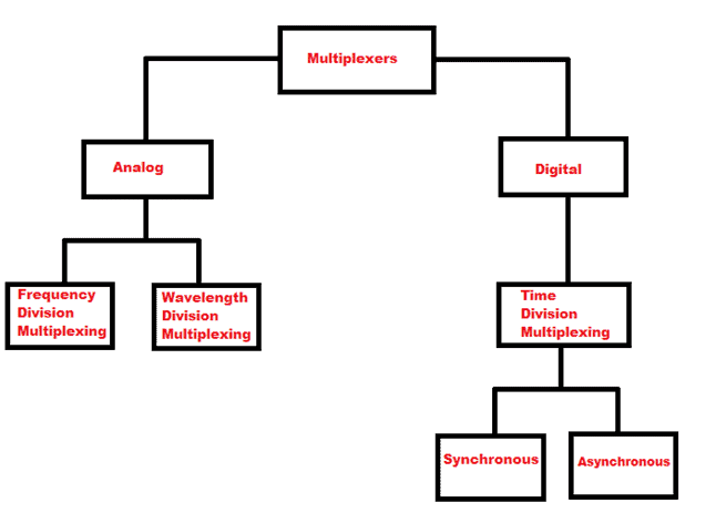
Types of Multiplexers
Frequency Division Multiplexing (FDM)
It is a method of networking that shares the total available bandwidth of any communication channel by colluding them into many non-overlapping bands of frequency. It combines various modulated frequencies to the transmission after it carried the frequency to each data stream. It sends signals over a medium of any communication purpose by using multiple frequencies to dive into many streams of data.
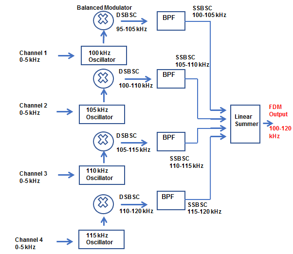
Frequency Division Multiplexing
As the figure shows, each channel occupies a different 5-kHz portion from the total combined bandwidth that is equal to 20kHz. The bandwidth of 10kHz is the output of the balanced modulator in a double-sideband suppressed-carrier waveform. The double sideband waveform is converted to a single sideband signal when it passes through a bandpass filter (BPF). In Channel 1, signals amplitude modulates a 100-kHz carrier in a balanced modulator that suppresses the 100-kHz carrier. In Channel 2, signal amplitude modulates a 105-kHz carrier in the balanced modulator. This produces a double sideband signal, which is then converted to a single-sideband every time it passes through a bandpass filter tuned to give only the upper sideband.
Wavelength Division Multiplexing (WDM)
It is partly similar to FDM. It sends information signals that initially occupied the same band frequencies through the same fiber at the same time without interference. It is a cooperation of two or more discrete wavelengths into and out of an optical fiber. In WDM, the wavelength spectrum that is used is in the region 1300 or 1500 mm. These are the two wavelength bands at which the optical fibers have the least amount of signal loss. WDM’s objective is to increase the bandwidth capacity of optical transmission media. It allows many optical signals to be transmitted simultaneously using a single fiber cable.
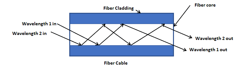
In the above figure, the propagation of each channel takes place in the same transmission medium at the same time. However, each channel occupies a different wavelength, and each wavelength takes a different transmission path.
Time Division Multiplexing (TDM)
TDM is very much different from WDM since the transmissions from multiple sources happen in the same facility but not at the same time. It allows the transfer of two or more streaming digital signals in a common channel. TDM is also known as digital circuit-switched. All the incoming signals are divided into equal fixed-length time slots and then transmitted over a shared medium and reassembled in its original form after de-multiplexing.
Applications of Multiplexers
Since a multiplexer allows the transmission of multiple data in a single line, it is preferred for various applications including the following:
- Telephone network – A multiplexer integrates the multiple audio signals into a single line of transmission in telephone networks.
- Transmission from the computer system of a satellite – A multiplexer can be used with a GSM communication to transmit the data signals to the ground system from the computer system of a satellite.
- Communication system – A multiplexer can become a transmission system and a communication network. It allows the transmission of data, such as audio and video data, from different channels via cables and single lines that helps increase the efficiency of the communication system.
- Computer memory – A multiplexer can be used to keep a huge amount of memory in the computer. It is also used best to decrease the number of copper lines necessary to connect the memory to the other parts of the computer.
How Does a Multiplexer Work?
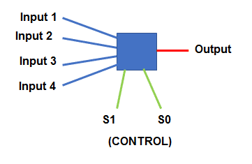
In this figure, the switch has four inputs with one output pin and you can select based on the signal given. It demonstrates the three basic parts of any multiplexer namely the input pins, output pins, and control signals.
- Input Pins – these are all the available input signals from which the best required signal has to e selected. It can be analog or digital.
- Output Pin – the chosen input signal will be provided by the output pin.
- Control/Selection Pin – this selects the input pin signal. The number of control pins depends on the number of input pins.
4×1 Multiplexer
As the name suggests, four-input multiplexers have four input lines and one output line. It has two control pins to select between the four available input pins.
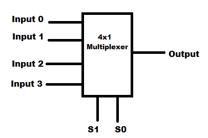
Any of the four inputs will be connected to the output based on the combination present at these two selection lines.
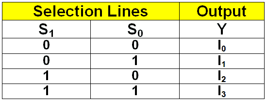
From the truth table above, you can come up with the Boolean equation for the output Y.
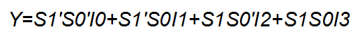
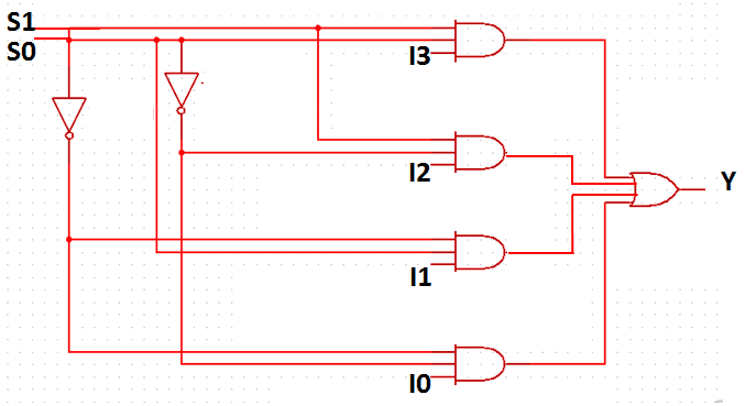
Given the Boolean function, we can implement the 4×1 multiplexer using inverters in this circuit diagram.
Implementing a Multiplexer With an MC14052B IC
The MC14052B has two 4×1 multiplexers inside. It is an analog multiplexer so the input pins can use variable voltage as supply but it will have the same result in the output pin.
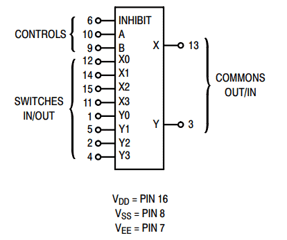
In the figure shown above, the control pins are A and B. It will be used to select the required input to the output pin. Pin 16 will serve as the Vdd for the supply voltage while pin 8 will be the ground or Vss. Pin X will be the corresponding output of the four input pins which are X0, X1, X2, and X3. Pin 7 or Vee pin will be for enabling and is an active low pin. Grounding is necessary to enable the IC.
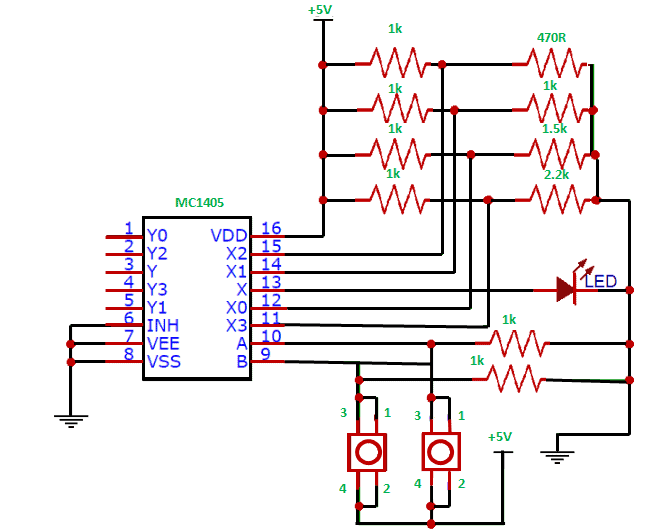
In the circuit above, a series of potential divider combinations were used to deliver variable voltages for pins 12, 14, 15, and 11. The use of two push buttons to control pins A and B will also determine if the circuit will work in a breadboard. As you can see, the output pin 13 is connected to the LED. The variation of its brightness based on the control signals will depend on the variable voltages supplied.
Thanks for reading! Be sure to leave a comment below if you have any questions!


