Out with the Arduino serial monitor and in with Adafruit IO. If you’re tired of seeing your sensor data on a plain white screen, then this tutorial is for you. Adafruit IO is going to make your data look like a million dollars and more!

The Fourth Industrial Revolution
The first industrial revolution ushered the discovery of the steam engine. Manufacturing was streamlined, giving time to researchers to make new things. Over a hundred years later came the second revolution, which introduced electricity, again hasting production. Then with even lesser time, the third revolution arrived along with the early computers and digital communication.
Now we’re living the fourth industrial revolution, also known as Industry 4.0. This era is still in the works, but the goal is to integrate technology into the daily lives of humanity. Things such as machine learning, artificial intelligence, 3D printing, autonomous vehicles, online banking, and even genome editing are some of the few gifts of this era. All of these are centered on a technology called IoT.
The Internet of Things
The Internet of Things (IoT) is a system of interconnected devices able to communicate with each other over a network without needing human-to-human or human-to-computer interaction. This is the heart of modern automation. An IoT system can comprise sensors, mobile devices, CCTVs, trains, or even your shower. IoT can connect anything. And with all the devices connected together, you can get data from one point to trigger an action on another point. You can just also harvest the data for analysis and improvement of the whole IoT system.
And the easiest way to practice IoT is by using an Arduino and a web service called Adafruit IO.
What is Adafruit IO?
Adafruit IO is a free IoT web platform made by Adafruit Industries. It functions as a control panel for all kinds of devices, including sensors built on an Arduino platform. It is designed not just for data visualization but for device control as well. With Adafruit IO, you can use graphs and charts to display your data as well as buttons and switches to trigger particular features on your device. Adafruit IO has well-documented client libraries that you can use to ease programming hours. Here are the other things you can do with the platform:
- real-time visualization of your data online;
- access your interface anywhere via the internet;
- connect your project to other web services and other internet-enabled devices.
Here are the terms you need to learn before we move on:
- Dashboard – offers graphs, charts, logs, and many more visualization techniques for your data.
- Trigger – reacts to your data. For example, you can use a trigger to send you an email when the temperature reading of a sensor exceeds a threshold value.
- Feed – contains the data you upload to Adafruit IO. The feed also holds the date and time when your data was uploaded.
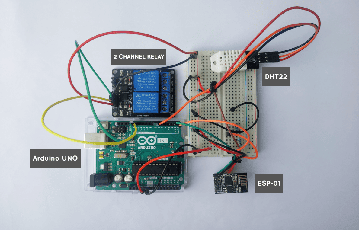
To demonstrate how to use Adafruit IO with the Arduino, we are going to interface a DHT22 humidity and temperature sensor and a two-channel 5V relay with an Arduino UNO, then transfer the temperature and humidity values to an ESP8266 module every 5 seconds. The ESP8266 module is set to update your Adafruit IO dashboard when it receives data from the Arduino.
Let us start by setting up Adafruit IO.
Setting Up Adafruit IO
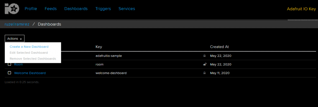
First, go to the Adafruit IO website and create an account. Once logged in, go to the home page. Under Actions, select Create a New Dashboard.
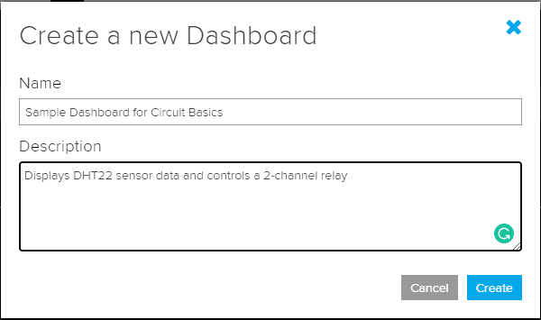
After giving the dashboard a name and a short description, click Create.
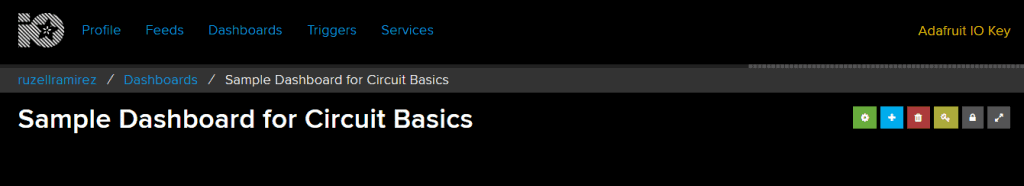
Next, go to your new Dashboard.
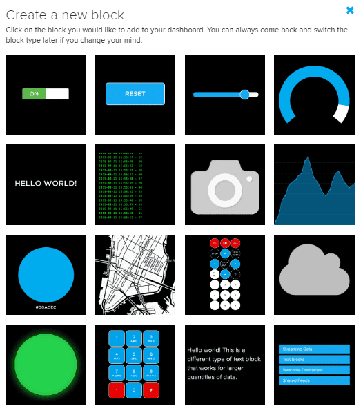
You will need to fill your dashboard with blocks. In order to do that, press the blue plus button on the right side of the dashboard.
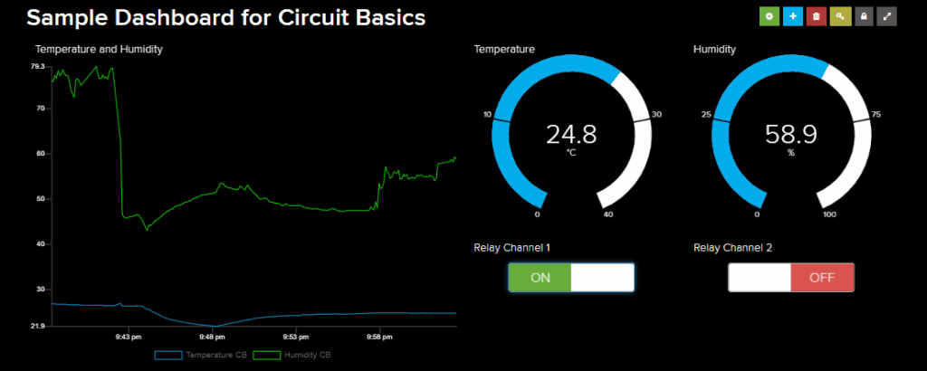
Blocks are switches, buttons, levers, gauges, and more visualization techniques that represent and react to your data. For our sample project, we need a line chart and two gauges to display the room’s temperature and humidity, and two buttons to control our relay.
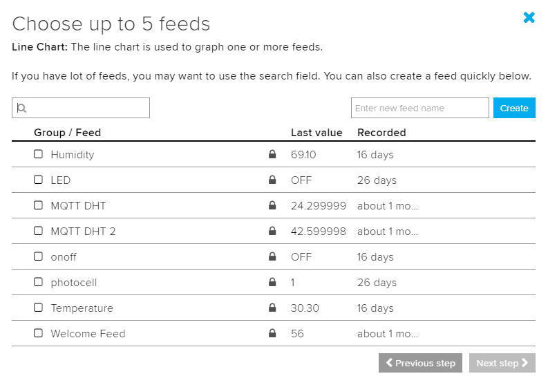
After selecting a block, Adafruit prompts you to choose a feed. We need two feeds to hold the temperature and humidity values of the DHT sensor. Create a feed using the create button on the right.
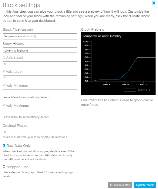
Next, configure the block settings as you please.
Do the same with the relay buttons so that you can control and monitor both data simultaneously.
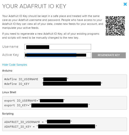
To fill the blocks with data, you will need your username and key. To obtain both information, go back to the homepage and click on Adafruit IO Key. A window will appear that displays your username and key. Grab a pen and paper and write them down.
Installing the Adafruit IO Library
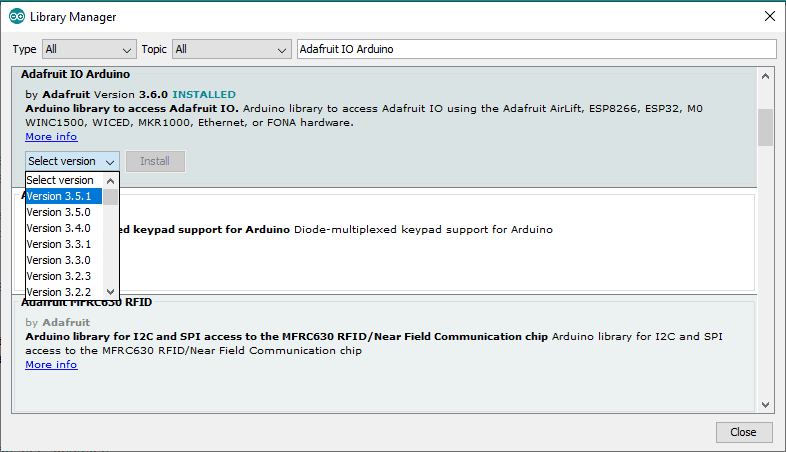
To install the library, go to Library Manager and search for “Adafruit IO Arduino”. Select the latest version and click Install. This is going to prompt you to install other libraries that Adafruit IO Arduino needs to work properly. Make sure to update your ESP8266 board library as well. Older versions of the board flag as errors when uploading the code.
Preparing the Hardware
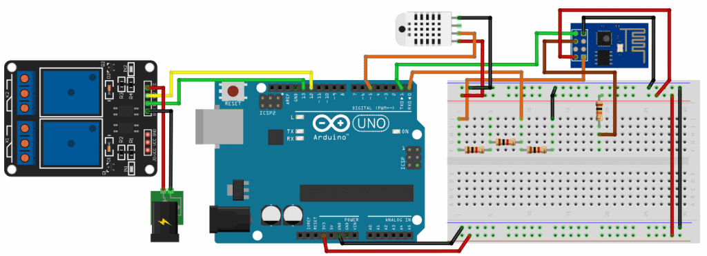
We are going to interface the DHT22 sensor and a two-channel 5V relay with the Arduino, then transfer the sensor readings to the ESP8266 module every 5 seconds. The ESP8266 module is set to update your Adafruit IO dashboard when it receives data from the Arduino.
Connect the following components as in the diagram below.
- Arduino UNO
- ESP8266-01 module
- DHT22 temperature and humidity sensor
- 3 x 1 kΩ resistor
- 1 x 10 kΩ resistor
- 2-channel 5V relay
- Jumper wires
- Breadboard
To learn more about the Arduino, check out our Ultimate Guide to the Arduino video course. We teach Arduino programming and circuit building techniques that will prepare you to build any project.
Code for the Arduino UNO
#include "SerialTransfer.h"
#include <DHT.h>

#define DHTPIN 5
#define DHTTYPE DHT22
DHT dht(DHTPIN, DHTTYPE);
float t,h;

SerialTransfer myTransfer;

void setup()
{
  Serial.begin(115200);
  dht.begin();
  pinMode(7, OUTPUT);
  pinMode(8, OUTPUT);
}

void loop()
{
  t = dht.readTemperature();
  h = dht.readHumidity();

  myTransfer.txObj(status, sizeof(t));
  myTransfer.sendData(sizeof(t));
  myTransfer.txObj(status, sizeof(h));
  myTransfer.sendData(sizeof(h));
  delay(5000);
  if(myTransfer.available())
  {
    digitalWrite(7, relay1status == "ON" ? HIGH : LOW);
    digitalWrite(8, relay2status == "ON" ? HIGH : LOW);
  }
}
Code for the ESP8266 Module
#include <ESP8266WiFi.h>
#include "AdafruitIO_WiFi.h"
#include "SerialTransfer.h"

SerialTransfer myTransfer;

#define WIFI_SSID "Wifi Name"
#define WIFI_PASS "WiFi Password"

#define IO_USERNAME "Your username"
#define IO_KEY "Your key"

AdafruitIO_WiFi io(IO_USERNAME, IO_KEY, WIFI_SSID, WIFI_PASS);

AdafruitIO_Feed *temperatureFeed = io.feed("Temperature CB");
AdafruitIO_Feed *humidityFeed = io.feed("Humidity CB");
AdafruitIO_Feed *relay1feed = io.feed("Relay Channel 1");
AdafruitIO_Feed *relay2feed = io.feed("Relay Channel 2");

void setup()
{
  Serial.begin(115200);
  io.connect();
  WiFi.mode(WIFI_STA);
  WiFi.begin(ssid, password);

  while (WiFi.status() != WL_CONNECTED) {
    delay(500);
  }
  relay1feed->onMessage(relay1control);
  relay2feed->onMessage(relay2control);
  relay1feed->get();
  relay2feed->get();
  myTransfer.begin(Serial);
}

void loop()
{
  if(myTransfer.available())
  {
    float t,h;
    myTransfer.rxObj(t, sizeof(t));
    myTransfer.rxObj(h, sizeof(h));
    temperatureFeed->save(t);
    delay(100);
    humidityFeed->save(h);
  }
}
void relay1control(AdafruitIO_Data *data)
{
   String relay1status = data->toString();
   Serial.print("Relay 1 is ");  Serial.println(relay1status);
   myTransfer.txObj(relay1status, sizeof(relay1status));
   myTransfer.sendData(sizeof(relay1status));
}
void relay2control(AdafruitIO_Data *data)
{
   String relay2status = data->toString();
   Serial.print("Relay 2 is ");  Serial.println(relay2status);
   myTransfer.txObj(relay2status, sizeof(relay2status));
   myTransfer.sendData(sizeof(relay2status));
}
Code for NodeMCU
#include <ESP8266WiFi.h>
#include "AdafruitIO_WiFi.h"
#include <DHT.h>

#define DHTPin D5
#define DHTType DHT22
DHT dht(DHTPin, DHTType);

#define WIFI_SSID "wifi name"
#define WIFI_PASS "wifi password"

#define IO_USERNAME "your username"
#define IO_KEY "your key"

AdafruitIO_WiFi io(IO_USERNAME, IO_KEY, WIFI_SSID, WIFI_PASS);

AdafruitIO_Feed *temperatureFeed = io.feed("Temperature CB");
AdafruitIO_Feed *humidityFeed = io.feed("Humidity CB");
AdafruitIO_Feed *relay1feed = io.feed("Relay Channel 1");
AdafruitIO_Feed *relay2feed = io.feed("Relay Channel 2");

void setup()
{
  Serial.begin(115200);
  io.connect();
  dht.begin();

  pinMode(D7, OUTPUT);
  pinMode(D8, OUTPUT);

  while(io.status() < AIO_CONNECTED)
  {
    Serial.print(".");
    delay(500);
  }

  relay1feed->onMessage(relay1control);
  relay2feed->onMessage(relay2control);
  relay1feed->get();
  relay2feed->get();
}

void loop()
{
  io.run();
  float t = dht.readTemperature();
  float h = dht.readHumidity();

  temperatureFeed->save(t);
  delay(100);
  humidityFeed->save(h);

  delay(5000);
}

void relay1control(AdafruitIO_Data *data)
{
   String relay1status = data->toString();
   Serial.print("Relay 1 is ");  Serial.println(relay1status);
   digitalWrite(D7, relay1status == "ON" ? HIGH : LOW);
}
void relay2control(AdafruitIO_Data *data)
{
   String relay2status = data->toString();
   Serial.print("Relay 2 is ");  Serial.println(relay2status);
   digitalWrite(D8, relay2status == "ON" ? HIGH : LOW);
}
Explanation of the Code
We are going to use the SerialTransfer.h library to send the sensor data from the Arduino UNO to the ESP module and vice versa. You can download it from here.
These are the important lines we’ve used from the library:
SerialTransfer myTransfer– creates a SerialTransfer instance called myTransfer.myTransfer.begin(Serial)– starts serial communication using baud rate Serial.myTransfer.txObj(status, sizeof(status))– creates an object specifically made for status.myTransfer.sendData(sizeof(status))– sends status in a packet right for its size.myTransfer.rxObj(status, sizeof(status))– receives status from the sender.
In this project, the UNO has two jobs. First, it has to read DHT sensor data then send it to the ESP module every five seconds. Second, it must wait for an input from Adafruit IO to activate or deactivate a particular channel in the two-channel relay. Just like before, we interface the DHT sensor using the DHT.h library, which you can get from this link. In order to properly use the library, you need to specify the pin where the sensor is connected and the type of DHT sensor you’re using. Then, we create a DHT object using these two. The code should look like this: DHT dht(DHTPIN, DHTTYPE). After creating the object, we initialize the sensor using dht.begin() to use functions like dht.readTemperature() and dht.readHumidity. Finally, we use the SerialTransfer.h to send the data to the ESP module.
On the other hand, another job of the ESP module is to detect the incoming data from the Arduino and send them to Adafruit IO’s server. Additionally, it should receive the status of the relay button from the Adafruit IO dashboard and send it to Arduino UNO. We use io() to connect the ESP module to the Adafruit IO server. Next, we specify the feeds we’re going to interact with using io.feed(). We have a total of 4 feeds for the temperature and humidity values, and the status of each channel in the relay module. We use onMessage() and get() to call the helper function for the relay button and fetch data from it. Next, the loop section must include io.run() to keep the communication online. To send the temperature and humidity values to Adafruit IO, we use save().
Demonstration
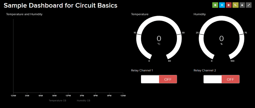
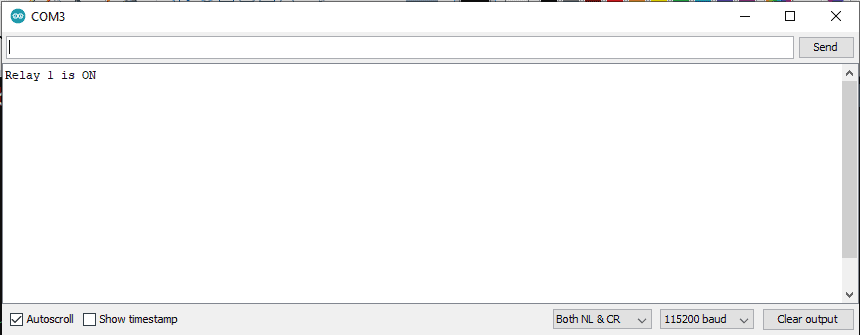
Your Arduino will populate the dashboard as soon as it connects to the Adafruit IO server. I’ve let the device send data for about 15 minutes then I pressed the button for Relay Channel 1.
I said earlier that the serial monitor is plain but it’s actually pretty useful. As you can see, the Arduino detected the high signal from Adafruit IO so it turns Relay 1 on.
Hope this makes it easier for you to make a web based IOT control panel with your Arduino. If you have any questions, feel free to leave a comment below.


is it possible to use esp-32 module instead of ESP8266-01 module ?
Yep, it is. Adafruit IO’s library is compatible with ESP32.
OK , sounds good… i have one “free” esp-32 module … project is very interesting … I’m gonna test it in near future
all the best and thank’s for your answer !
Hello. I am currently implementing this project. I do not know exactly where to enter the names of elements correctly when creating the desktop. So that when transmitting data, Adafruit knows to what elements to assign the received data. I noticed that each element has a unique link, couldn’t it be used in the code?
Hola, consulta? por que aparecen 3 codigos? Si en el diagrama aparece solo el arduino uno y el ESP8266 ?? tengo que cargar ambos programas en cada uno o No ???
Replacing the Arduino UNO and the ESP01 with a better ESP device (such as Wemos D1 Mini) would significantly simplify the hardware design, remove the MCU-MCU interfacing requirements, simplify the software requirements, significantly reduce the overall project volume, provide a WiFi device that is actually breadboard friendly and reduce the costs significantly.
Although the ESP01 was designed for exactly this purpose (a WiFi Modem for devices without generic WiFi). It is not a good solution for new projects. And certainly not for educational purposes.