Magnetometers measure the magnetic field along one or more axes. With a magnetometer, you can turn your Arduino into a digital compass. They’re great for navigation and guidance systems in remote controlled vehicles. You can even use them to detect electric currents in wires.

In this article, we’re going to use a magnetometer to build a digital compass on the Arduino. But before we get into that, there’s something I have to warn you about. The most well documented magnetometer for the Arduino is the HMC5883L. When researching this article, I found an HMC5883L on eBay and ordered it. But no matter what I tried, I couldn’t get it to work. Then I discovered that even though my magnetometer was labelled as an HMC5883L, it was actually a QMC5883L. Libraries written for the HMC5883L don’t work with the QMC5883L. So when you’re buying a magnetometer online, there’s a good chance that your HMC5883L is actually a QMC5883L. There are already lots of tutorials online for the HMC5883L, so in this article we will see how to set up and program the QMC5883L magnetometer.
Watch the video for this tutorial here:
Overview of the QMC5883L Magnetometer
The QMC5883L has 5 pins – Vcc, ground, SCL, SDA, and DRDY:
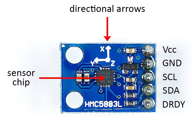
The sensor chip is on top of the board. Magnetometers and other directional sensors will have arrows on them. These show you the orientation of the sensor in relation to the PCB. This magnetometer detects magnetic fields in three axes – x, y, and z. The z axis points up and down, perpendicular to the x and y axes.
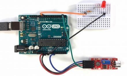
How to Connect the QMC5883L Magnetometer to the Arduino
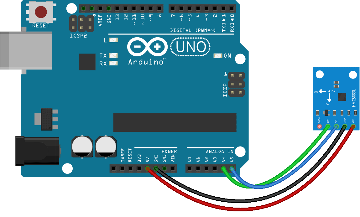
The QMC5883L uses I2C to communicate with the Arduino, so only two data wires and two power wires are needed to connect it.
Here are the parts needed:
Connect the magnetometer to the Arduino like this:
How to Program a QMC5883L Magnetometer on the Arduino
We will use a library from Sunfounder to program the magnetometer. Download it from the resource section of this webpage. Once you download and install the library, upload the code below to the Arduino.
The program will output the raw values from each axis of the magnetometer to the serial monitor:
#include <Wire.h>
#include <QMC5883L.h>

QMC5883L compass;

void setup() {
  Wire.begin();
  Serial.begin(9600);
  compass.init();
}

void loop() {
  int x, y, z;

  compass.read(&x, &y, &z);

  Serial.print("x: ");
  Serial.print(x);
  Serial.print("    y: ");
  Serial.print(y);
  Serial.print("    z: ");
  Serial.println(z);

  delay(250);
}
Explanation of the Code
Since the magnetometer uses I2C, we need to include the Wire library. We also need to include the QMC5883L library. Next we create an object called compass which is a member of the QMC5883L class so we can access the functions in the library.
In the setup() section, we initialize the I2C interface with Wire.begin(). Then we initialize the serial monitor and initialize the compass object with the init() function from the QMC5883L class.
In the loop() section, we need to declare a few int variables. The QMC5883L outputs separate magnetism readings for each axis. So let’s declare variables for each axis – x, y, and z. Now we can get the readings from the sensor.
The QMC5883L library has a function called read() that pulls in the values from the sensor. The read() function takes three parameters. The first parameter is the variable that will store the reading from the sensor’s x axis. The second parameter is the variable that will store the reading from the sensor’s y axis. The third parameter is the variable that will store the z axis reading.
Now we just need to print the x, y, and z variables to the serial monitor. So we have a series of Serial.print() functions to print the x, y, and z variables. At the end of the loop, we delay for 250 milliseconds to slow down the output a little.
Once the magnetometer is connected and the code is uploaded to the Arduino, open up the serial monitor:
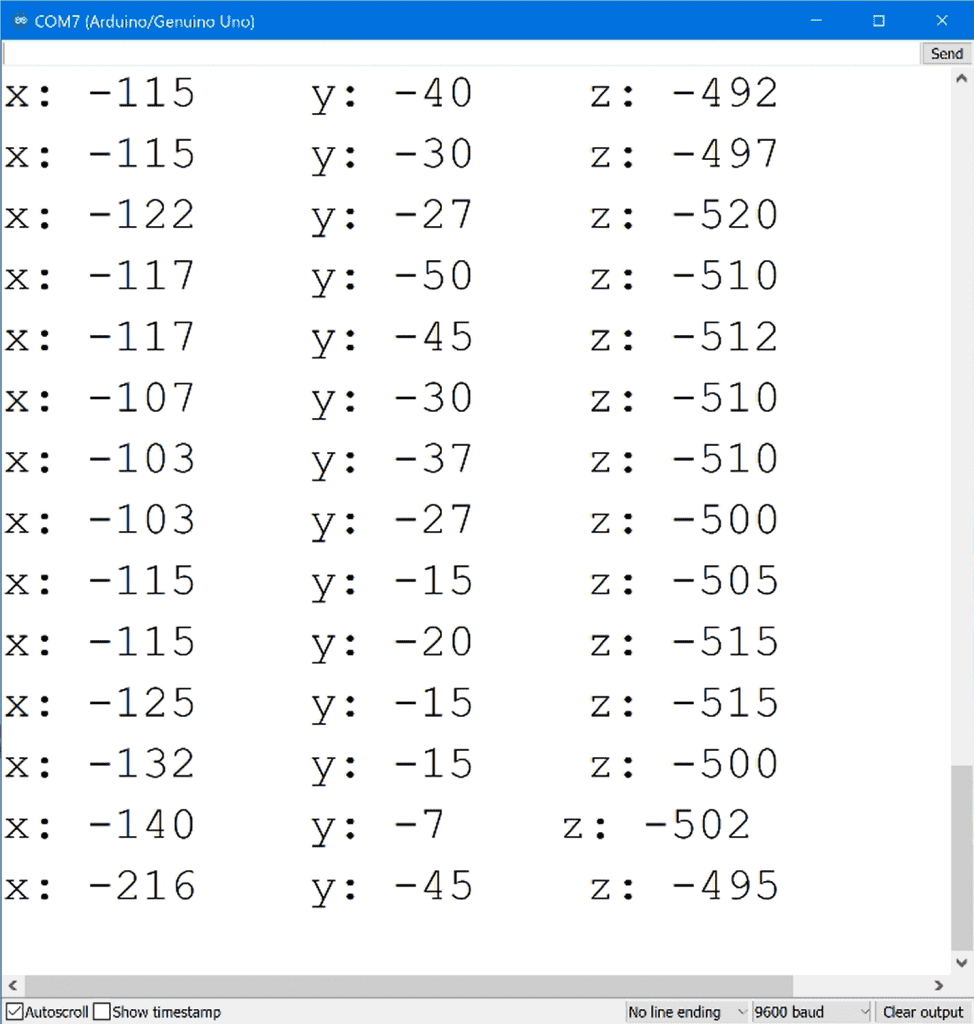
The raw values you see here are the magnitudes of the magnetic field along each axis in microteslas.
If you have a bar magnet, place the north pole of the magnet in front of the x axis and you should see the x value decrease significantly. If you put the magnet in front of the y and z axes, the values should decrease too.
But even without the magnet, the sensor is sensitive enough to detect the earth’s own magnetic field. So now let’s use these readings to get a compass heading.
How to Make a Digital Compass with the QMC5883L and an Arduino
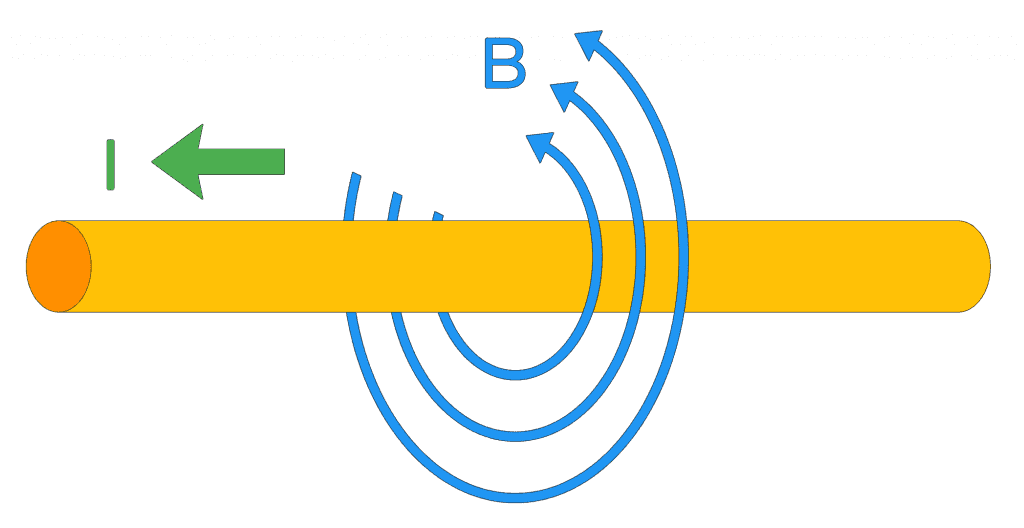
Magnetic fields are created by a variety of sources. An electric current flowing through a wire creates a magnetic field:
But the magnetic field you’re probably most familiar with is the one created by the Earth’s iron core:
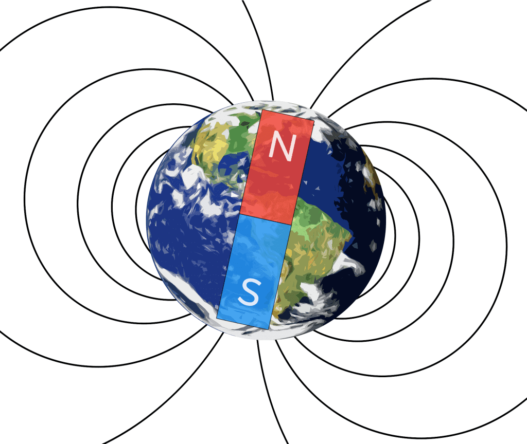
The Earth’s magnetic field surrounds the entire globe and allows us to use a compass as a tool for navigation.
True North vs Magnetic North
The north direction you see on a map is pointing to true north, which is aligned to the Earth’s axis of rotation:
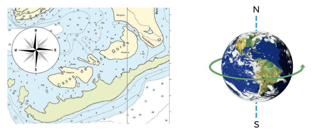
True north points directly to the north pole. But a compass points to the Earth’s magnetic north pole, not the north pole of the Earth’s rotation:
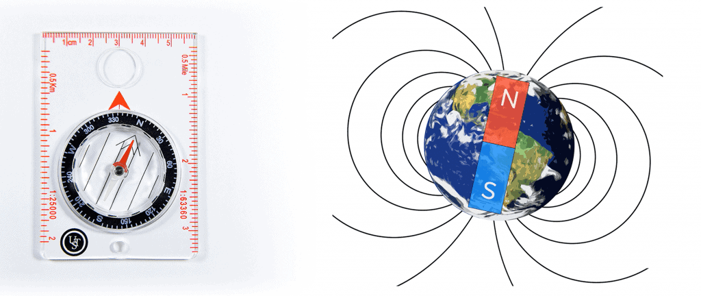
Currently, the magnetic north pole is about 310 miles away from the true north pole. This means that the north we use for navigation is different from the north that a compass needle points to. The difference between these two directions is called the angle of magnetic declination:
The angle of declination depends on your location on Earth. It can be up to 15 degrees off of true north. To relate the north reading of a compass to north on a map, we take the degree heading from a compass and add the angle of declination to it.
Code for the Arduino QMC5883L Compass
The sketch below will take the magnetometer readings from each axis and output a compass heading in degrees. It also displays the cardinal directions N, S, E, and W. Once the magnetometer is connected, upload this code to the Arduino:
#include <Wire.h>
#include <QMC5883L.h>

QMC5883L compass;

void setup() {
  Wire.begin();
  Serial.begin(9600);
  compass.init();
}

void loop() {
  int x, y, z;
  String cardinal;

  compass.read(&x, &y, &z);

  float headingRadians = atan2(y, x);
  float headingDegrees = headingRadians * 180 / PI;
  float declinationAngle = 11.41666666666667;

  headingDegrees += declinationAngle;

  if (headingDegrees < 0) {
    headingDegrees += 360;
  }

  if (headingDegrees > 348.75 || headingDegrees < 11.25) {
    cardinal = " N";
  }
  else if (headingDegrees > 11.25 && headingDegrees < 33.75) {
    cardinal = " NNE";
  }
  else if (headingDegrees > 33.75 && headingDegrees < 56.25) {
    cardinal = " NE";
  }
  else if (headingDegrees > 56.25 && headingDegrees < 78.75) {
    cardinal = " ENE";
  }
  else if (headingDegrees > 78.75 && headingDegrees < 101.25) {
    cardinal = " E";
  }
  else if (headingDegrees > 101.25 && headingDegrees < 123.75) {
    cardinal = " ESE";
  }
  else if (headingDegrees > 123.75 && headingDegrees < 146.25) {
    cardinal = " SE";
  }
  else if (headingDegrees > 146.25 && headingDegrees < 168.75) {
    cardinal = " SSE";
  }
  else if (headingDegrees > 168.75 && headingDegrees < 191.25) {
    cardinal = " S";
  }
  else if (headingDegrees > 191.25 && headingDegrees < 213.75) {
    cardinal = " SSW";
  }
  else if (headingDegrees > 213.75 && headingDegrees < 236.25) {
    cardinal = " SW";
  }
  else if (headingDegrees > 236.25 && headingDegrees < 258.75) {
    cardinal = " WSW";
  }
  else if (headingDegrees > 258.75 && headingDegrees < 281.25) {
    cardinal = " W";
  }
  else if (headingDegrees > 281.25 && headingDegrees < 303.75) {
    cardinal = " WNW";
  }
  else if (headingDegrees > 303.75 && headingDegrees < 326.25) {
    cardinal = " NW";
  }
  else if (headingDegrees > 326.25 && headingDegrees < 348.75) {
    cardinal = " NNW";
  }

  Serial.print("Heading: ");
  Serial.print(headingDegrees);
  Serial.println(cardinal);

  delay(250);
}
Explanation of the Code
The sketch starts out the same way as the first sketch – we include the Wire library and the QMC5883L library, then create a compass object. Then we initialize the I2C interface, initialize the serial monitor, and initialize the magnetometer.
In the loop() section, we declare local int variables for each axis, x, y, and z. Later in the sketch, we’re going to convert the heading in degrees to cardinal directions so we create a String object called cardinal to store the cardinal direction values.
Next, we get the magnetometer readings for each axis with compass.read(), and store the readings in the x, y, and z variables.
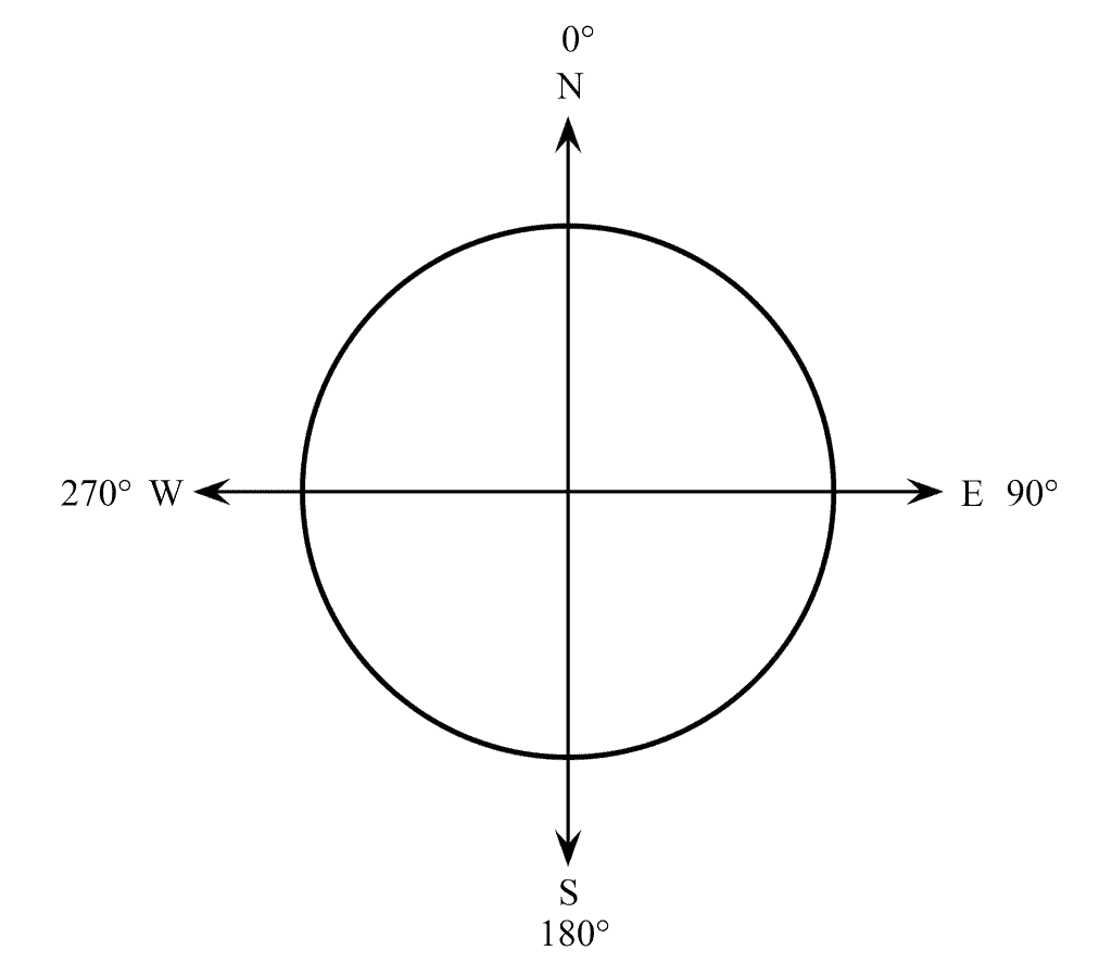
To see how the x, y, and z readings are converted to a direction in degrees, let’s take a look a compass rose. In every compass, north is at 0°, east is at 90°, south is at 180°, and west is at 270°:
If we point the x axis of the sensor in the direction we want to travel:
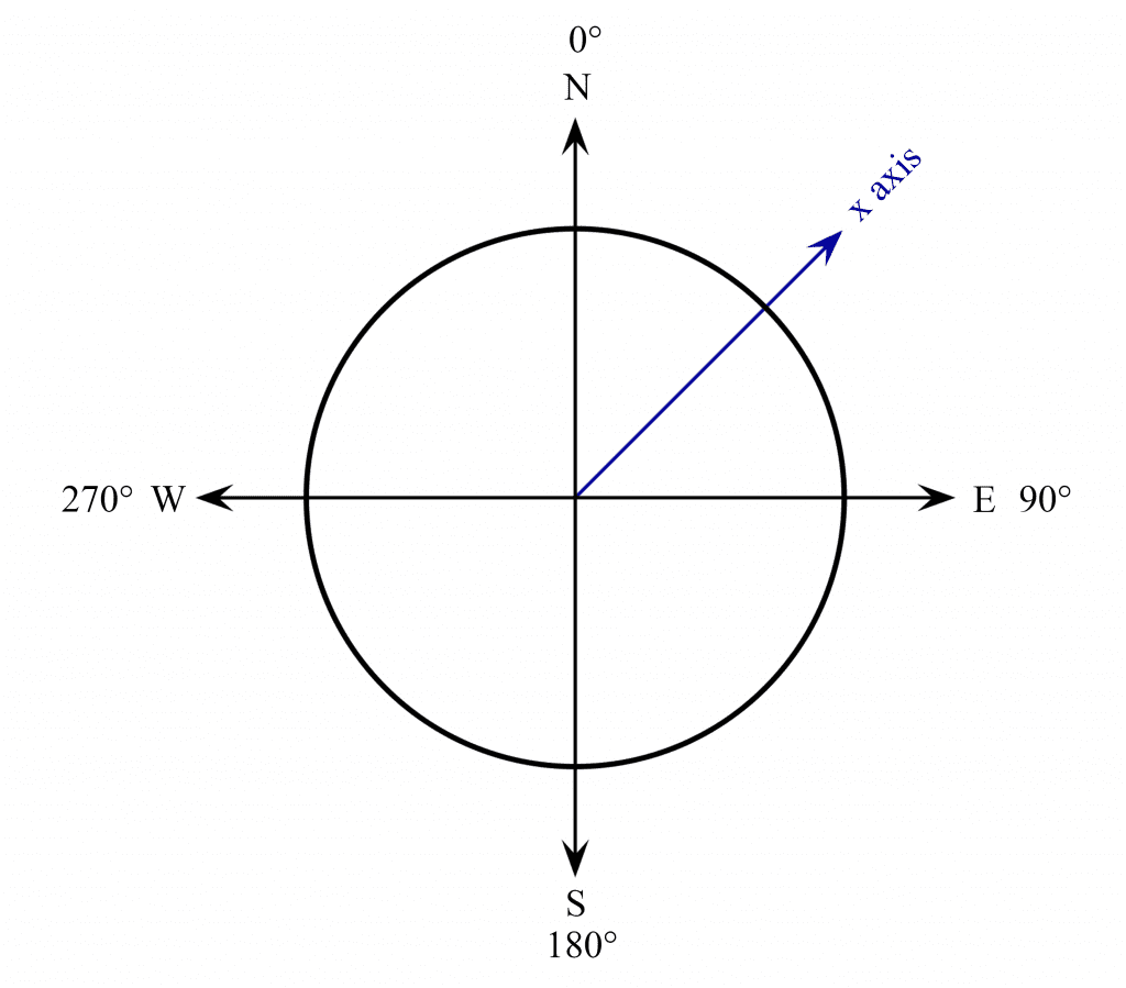
An angle is formed between 0° north and the direction the x axis is pointing:
If we think of the sensor’s x and y axes forming a unit circle, we can see that the north direction arrow has an x component and a y component:

The x component is the output of the magnetometer’s x axis in microteslas. And the y component is the output of the magnetometer’s y axis in microteslas.
The angle between 0° north and the x axis of the sensor can be found with a trigonometry function called atan2(). The atan2() function takes the magnitudes of the x and y sensor outputs, and returns an angle in radians. This is your heading in radians:
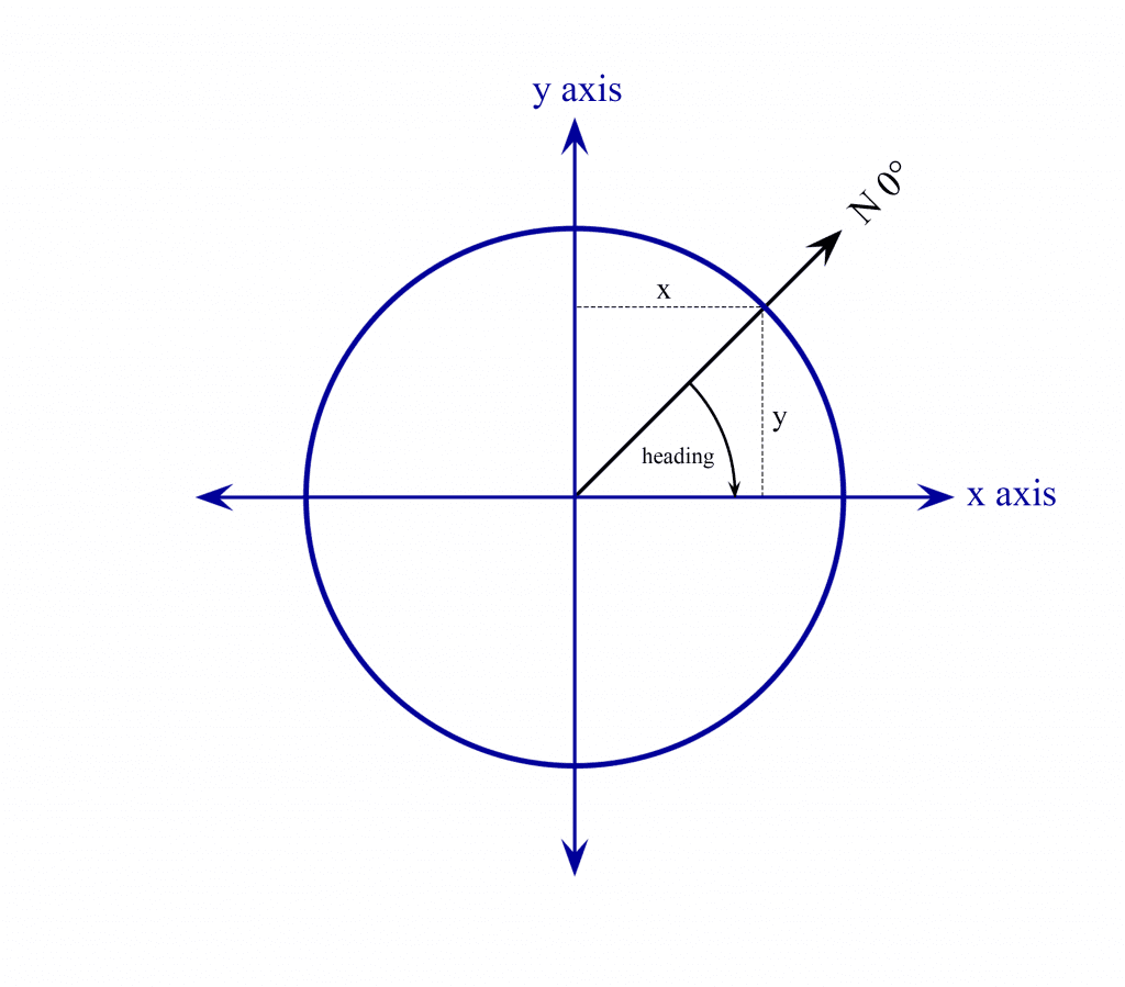
In the loop() section of the sketch above, we declare a float variable called headingRadians to store the outputs of the atan2() function with the x and y axes values. Next we use the formula float headingDegrees = headingRadians * 180 / PI to convert radians to degrees. The result will be stored in another float variable called headingDegrees. Now we have the angle that the x axis of the sensor is pointing, relative to north at 0°.
How to Add Magnetic Declination to Compass Readings
Now we need to add the magnetic declination. To find the magnetic declination of your current location, visit www.magneticdeclination.com.
The magnetic declination will be provided in degrees and minutes, so you’ll have to convert the minutes value to degrees and add that to the degrees value. Minutes are just a fraction of a degree. There are 60 minutes in one degree. All you have to do is divide your minutes value by 60 to get the fractional degree component, then add that to the degree value. Enter your calculated magnetic declination into the line that says float declinationAngle =.
On the next line, we take the headingDegrees variable, and use a compound addition operator to add the declination angle to it. Now we have a heading in degrees that has been adjusted for the magnetic declination. But there’s one little quirk about the atan2() function. It only returns angles between 0° and 180° degrees, and 0° to -180°:
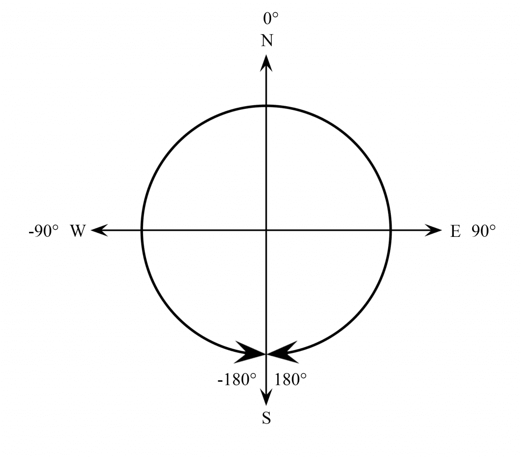
In this situation, north is still 0° and east is still 90° degrees. But west is now -90° and south is now +180° or -180°. If the x axis of the sensor is pointing south west, the output of atan2() will be -135°:
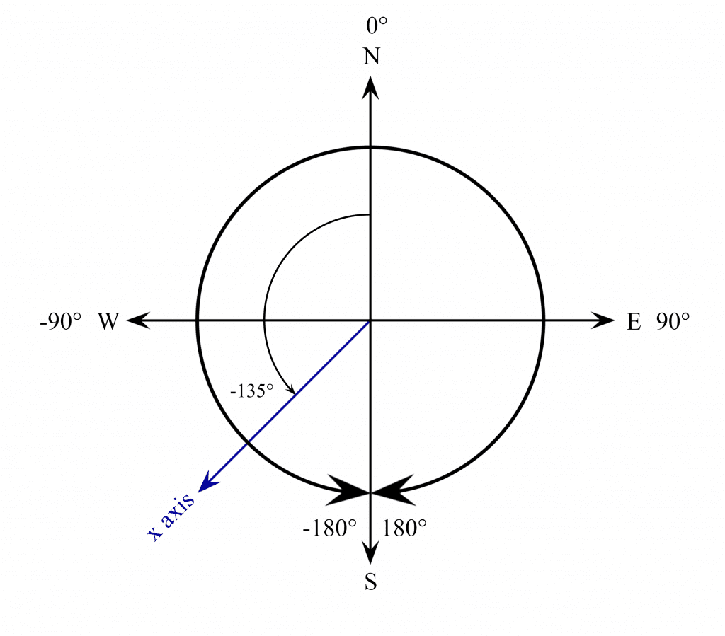
But on a compass, this direction would be 225°. So we need to convert the value of headingDegrees to a value between 0° and 360°, just like it is on a compass. To do that, all we need to do is add 360° to the heading when the value is less than zero. We do that with an if statement. The if statement says “if headingDegrees is less than zero, do a compound addition to add 360° to the headingDegrees variable”. This is easier to visualize with a diagram:
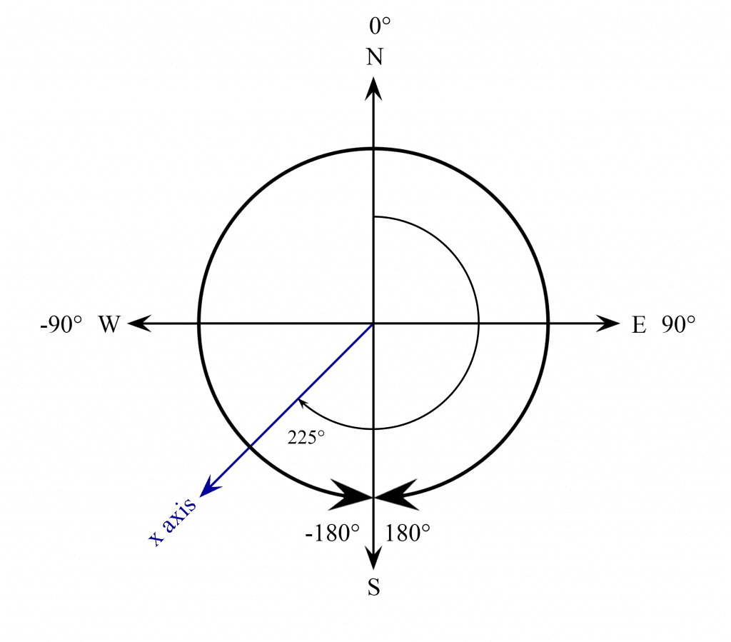
You can see how adding 360° to -135° degrees makes the angle 225°, without changing its position. So at this point, the sensor will output an angle from 0° to 360°, depending on where the x axis is pointing.
Having a heading in degrees is nice, but compasses also tell you the cardinal direction:
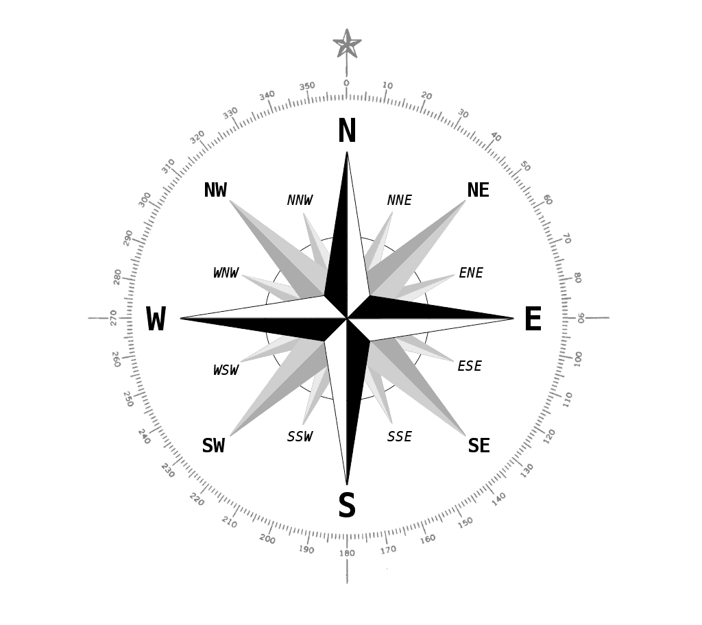
Let’s make this compass display the heading in degrees and the cardinal direction. To do that, we will divide the compass into multiple ranges of degrees:
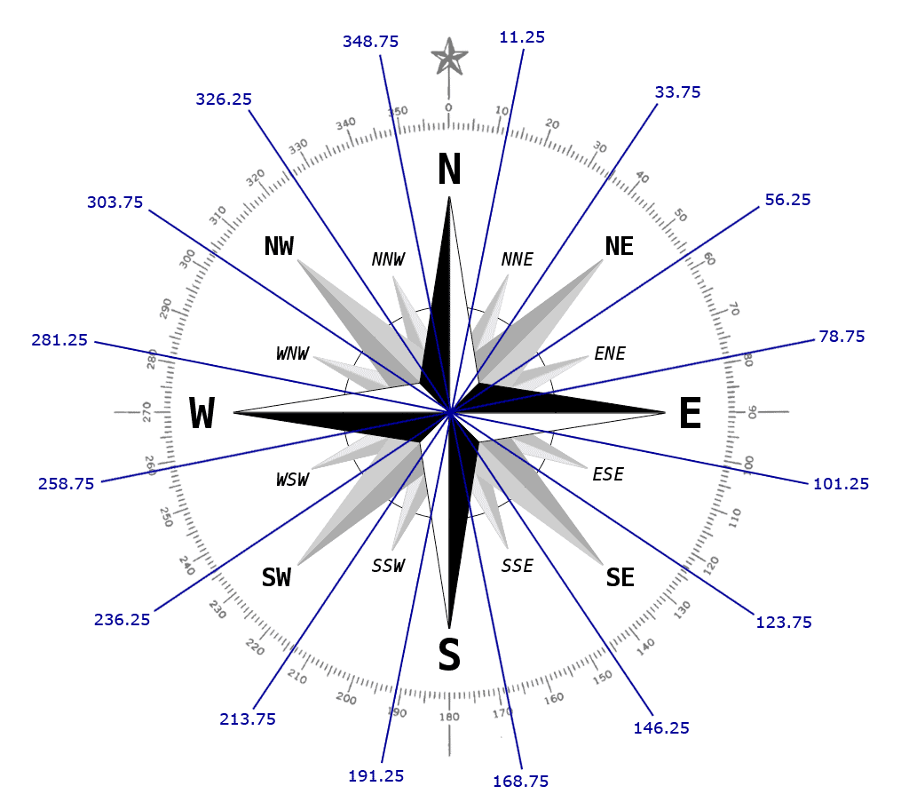
So for example, when the x axis of the magnetometer is pointing anywhere between 303.75° and 326.25° degrees, we’ll print some text that says “NW” for north west. And when the sensor is pointing anywhere between 101.25° and 123.75°, we’ll print some text that says east south east.
We’ll use a series of if and else if statements to display the cardinal direction when the heading is within that range of degrees. We start with an if statement that says “if headingDegrees is greater than 348.75° or less than 11.25°, set cardinal equal to the letter N for north”.
Then we have a series of else if statements that say “if headingDegrees is greater than 11.25° and less than 33.75°, then set cardinal equal to the letters NNE for north north east. We do the same thing for each cardinal direction.
After we define the range of degrees for each cardinal direction, we print the results to the serial monitor with Serial.print(headingDegrees) and Serial.println(cardinal). To make the output print to a new line the next time through the loop, we use Serial.println() where we want the line break to be. Then we add a 250 millisecond delay to slow down the output a little bit.
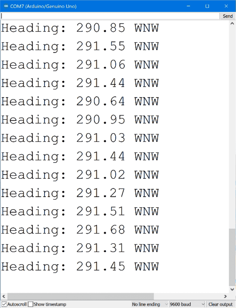
Once the magnetometer is connected to your Arduino, upload the sketch above and open up the serial monitor. You should see the heading in degrees and cardinal direction being printed out:
As you can probably tell, magnetometers are really useful sensors. If you have a remote controlled vehicle, you could use the heading to control which direction the vehicle travels. Or you could connect it to a weathervane to detect which direction the wind is blowing.
Thanks for reading! Be sure to leave a comment below if you have questions about anything…


Clearing the workbench and retry setting up compass using your guide. Thanks for publishing guide.