In this tutorial, we’ll discuss what the I2C communication protocol is, how it works, and how to use it on the Arduino. To demonstrate, we’re going to build a project that uses I2C communication to exchange data between two Arduino microcontrollers.

What is I2C?
I2C is an acronym for Inter-Integrated Circuit. I2C is a low-speed serial communication protocol used for transferring data over short distances. If you need to transfer data over a large distance, this protocol is not recommended.
An example of a simple I2C network is shown below:
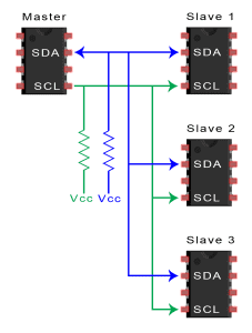
As you can see in the diagram above, the advantage of using I2C is that you only need two wires to communicate with multiple devices. All data passes through the two wires to and from the master and slave devices. Since the Arduino has a limited number of input/output pins, I2C can allow you to connect more devices.
Many Arduino sensors and modules are enabled for I2C communication.
The I2C Network
An I2C network consists of a master device and a slave device. The master and slave devices are connected by a bus. I2C networks can have multiple master devices and slave devices.
Slave Devices
Each slave device has an I2C address that is used to identify the device. The I2C address makes it possible for a master device to send data to a particular slave device on the bus.
Master Devices
Master devices can send and receive data. Slave devices respond to whatever a master device sends. When sending data on the bus, only one device can send data at a time.
The Bus
An I2C bus is simply two wires that connect all of the I2C devices in the network. The two wires are called SDA and SCL. The SDA wire is used for sending the actual data back and forth between the master and slave devices. The SCL line carries the clock signal used for communication timing. Pull-up resistors are used to keep both wires in a HIGH state by default.
Logic Levels
The Arduino outputs I2C signals at a 5V logic level. But I2C devices can operate at a range of different logic level voltages. An I2C device that operates at 3.3V could be damaged if connected to the Arduino. The device’s datasheet should tell you it’s logic level voltage.
To learn more about the details of I2C communication, check out our article on the Basics of the I2C Communication Protocol.
Making the Arduino Talk I2C
To demonstrate how to use I2C on the Arduino, let’s build a project that sends data back and forth between two Arduinos. This project will read the position of a potentiometer connected to a master Arduino, send the information over I2C, and change the blink rate of the LED on the slave Arduino.
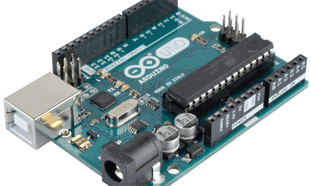
Arduino I2C Pins
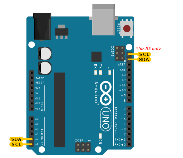
The Arduino has dedicated pins for I2C, which have built-in pull-up resistors as required by the I2C protocol.
For Arduino Uno boards, these are pins A4 and A5. Pin A4 is the SDA pin, and pin A5 is the SCL pin. In the Arduino Uno R3 version, there is another set of I2C pins near the USB socket:
Hardware Components
To build this project, you’ll need the following parts:
- Arduino Uno – 2 pcs.
- Potentiometer (10K Ohm) – 2 pcs.
- Jumper wires
- Breadboard
Wiring Diagram
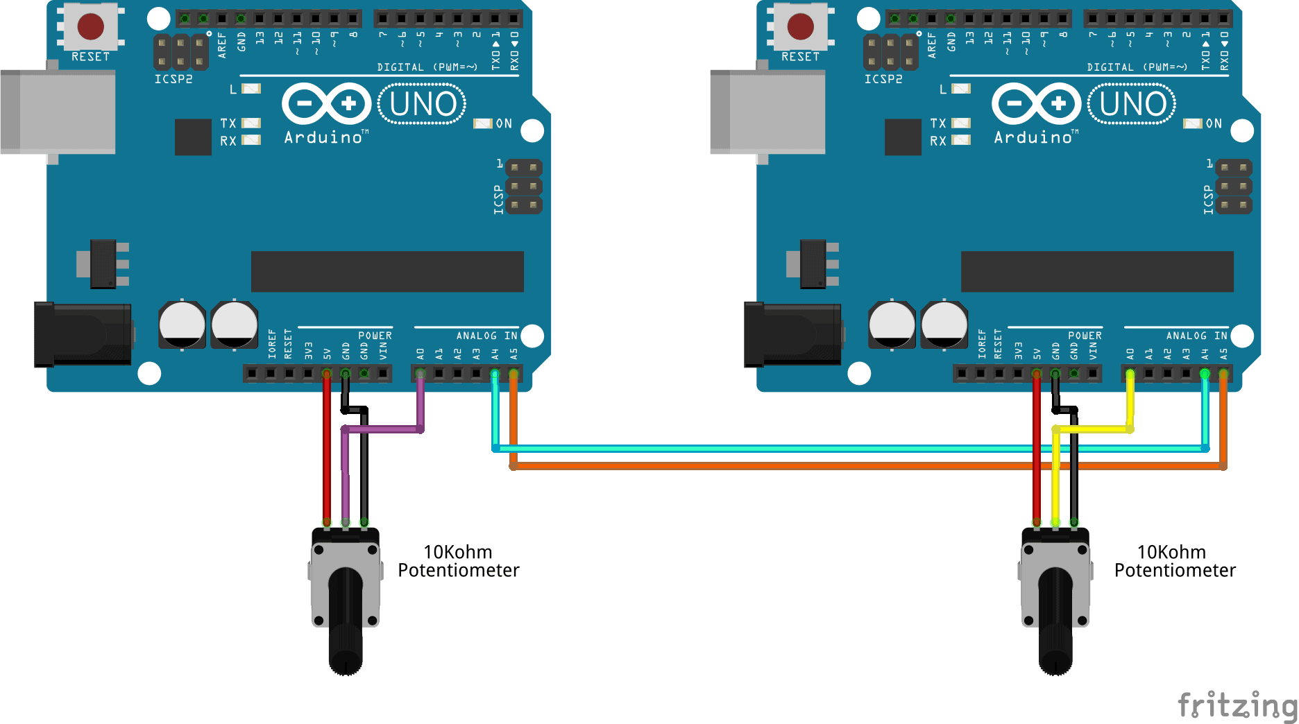
After you gather the parts, it’s time to assemble the project. Follow the wiring diagram below to connect everything:
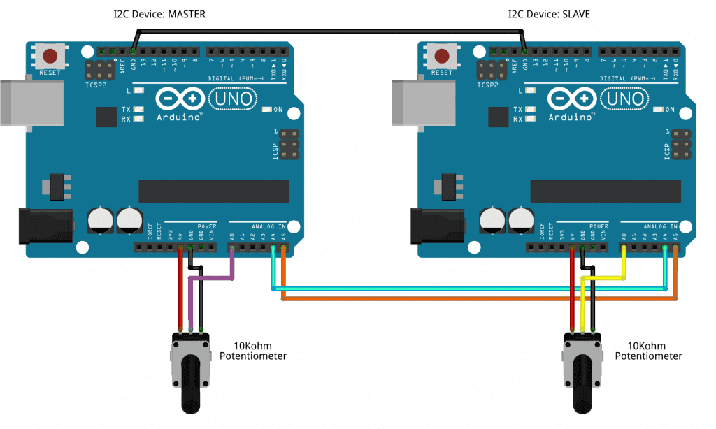
We don’t need pull-up resistors on the SDA and SCL lines, because they’re built into the Arduino’s I2C pins already.
Sketch for the Arduino Master Device
We have two Arduinos in our I2C network, so we have two sets of sketches. One is for the master Arduino, and the other is for the slave Arduino.
Open the Arduino IDE and upload the code below to the master Arduino:
// Arduino master sketch

#include <Wire.h>

byte i2c_rcv;               // data received from I2C bus
unsigned long time_start;   // start time in milliseconds
int stat_LED;               // status of LED: 1 = ON, 0 = OFF
byte value_pot;             // potentiometer position

void setup(){
	Wire.begin(); // join I2C bus as the master

	// initialize global variables
	i2c_rcv = 255;
	time_start = millis();
	stat_LED = 0;

	pinMode(13, OUTPUT);    // set pin 13 as an output
}

void loop(){
	// read potentiometer position
	value_pot = analogRead(A0);   // read the voltage at pin A0 (potentiometer voltage)

	// send potentiometer position to Slave device 0x08
	Wire.beginTransmission(0x08); // informs the bus that we will be sending data to slave device 8 (0x08)
	Wire.write(value_pot);        // send value_pot
	Wire.endTransmission();       // informs the bus and the slave device that we have finished sending data

	Wire.requestFrom(0x08, 1);    // request potentiometer position from slave 0x08
	if(Wire.available()) {	      // read response from slave 0x08
		i2c_rcv = Wire.read();
	}

	// blink logic code
	if((millis() - time_start) > (1000 * (float)(i2c_rcv/255))) {
		stat_LED = !stat_LED;
		time_start = millis();
	}
	digitalWrite(13, stat_LED);
}
Explanation of the Code
The basic part of the code for both the master and slave devices is what I call the blink logic code. To blink the pin 13 LED on the Arduinos, we need to do the following:
- Add global variables
byte i2c_rcv,int time_start,stat_LEDandbyte value_potat the top of our sketch - Initialize values of the global variables inside the
setup()section - Initialize pin 13 of the Arduino as an output pin using
pinMode() - Add the blink logic code inside the
loop()
The Wire Library
To use the Arduino’s built-in I2C interface, we will use the Wire library. This library is included with the Arduino IDE, so there’s no need to install it.
The Wire library has ready-made I2C functions to make the programming easier for us. To use the functions in the Wire library, we first need to add it to our sketch. In the sketch above, we do that with #include <Wire.h>.
After including the library, the next thing to do is to join the device on the I2C bus. The syntax for this is Wire.begin(address). The address is optional for master devices. So, for the master Arduino sketch, we just add the code Wire.begin(); inside the setup() function.
Now in the loop() section, the code will make the Arduino read the potentiometer value connected to pin A0, and save that value in the variable value_pot.
Sending Data Over I2C
After saving the value from pin A0 in the variable value_pot, we can send the value over I2C. Sending data over I2C involves three functions:
Wire.beginTransmission()
Wire.write()
Wire.endTransmission()
Wire.beginTransmission()
We initiate a send command by first informing the devices on the bus that we will be sending data. To do this, we call the function Wire.beginTransmission(address). The address is the I2C address of the slave device that will receive the data.
This function does two things:
- It informs the bus that we will be sending data
- It notifies the slave to prepare to receive the data
Wire.write()
Then we send the value stored in the value_pot variable using the function Wire.write(value). The value argument is the variable that stores the data you want to send.
Wire.endTransmission()
After sending the data, we need to free up the network to allow other devices to communicate over the network. This is done with the function Wire.endTransmission().
Receiving Data Over I2C
The master Arduino also needs to receive the potentiometer position from the slave Arduino. To receive data over I2C, we use the following three functions:
Wire.requestFrom()
Wire.available()
Wire.read()
Wire.requestFrom()
The complete syntax to request data from a slave device is Wire.requestFrom(address, quantity). The address is the I2C address of the slave device we need to get data from, and quantity is the number of bytes we need. For our project, the slave device address is 0x08 and we need one byte. So inside the loop(), we use Wire.requestFrom(0x08, 1); to request one byte of data from slave 0x08.
After issuing the command Wire.requestFrom(0x08, 1), it should be followed by a read command to get the response from the I2C bus.
Write.available()
First, we check if there is data available on the bus. We do this by using the function Write.available() inside a conditional if() statement. The function Write.available() returns the number of bytes waiting to be read.
Wire.read();
To get the data available, we use the function Wire.read() and save the return value to the variable i2c_rcv. Each call to the function Wire.read() gets only one byte of data from the I2C bus.
Sketch for the Arduino Slave Device
Now upload this code to the slave Arduino:
// Arduino slave sketch

#include <Wire.h>

byte i2c_rcv;               // data received from I2C bus
unsigned long time_start;   // start time in mSec
int stat_LED;               // status of LED: 1 = ON, 0 = OFF
byte value_pot;             // potentiometer position

void setup(){
	Wire.begin(0x08);           // join I2C bus as Slave with address 0x08

	// event handler initializations
	Wire.onReceive(dataRcv);    // register an event handler for received data
	Wire.onRequest(dataRqst);   // register an event handler for data requests

	// initialize global variables
	i2c_rcv = 255;
	time_start = millis();
	stat_LED = 0;

	pinMode(13, OUTPUT);        // set pin 13 mode to output
}

void loop(){

	value_pot = analogRead(A0); // read analog value at pin A0 (potentiometer voltage)

	// blink logic code
        if((millis() - time_start) > (1000 * (float)(i2c_rcv/255))) {
		stat_LED = !stat_LED;
		time_start = millis();
	}
	digitalWrite(13, stat_LED);
}

//received data handler function
void dataRcv(int numBytes){
	while(Wire.available()) {	// read all bytes received
		i2c_rcv = Wire.read();
	}
}

// requests data handler function
void dataRqst(){
	Wire.write(value_pot); // send potentiometer position
}
Explanation of the Code
For the slave device, there is a slight difference in the code. The first difference is with Wire.begin(address). For slave devices, the address is a requirement. For our project, the address for the slave device will be 0x08. It can be any address you want, but make sure it is unique in the I2C network. Some I2C slave devices also have their I2C addresses defined, so check the datasheet first.
We will join the I2C network as a slave device by adding the code Wire.begin(0x08); inside the setup() section.
Event Handlers
The next task is to add event handlers to our code to manage the data received from other devices in the I2C network. Event handlers are pieces of code that manage events that our device will likely encounter while running.
Wire.onReceive()
In the setup() part of the sketch, we add the function Wire.onReceive(handler) to register a function (the handler) that will manage the data received. we’ll call our handler function dataRcv(). Take note that the function name can be anything you want. In the sketch above, Wire.onReceive(dataRcv); in called in the setup() section. At the end of the sketch is the code for the handler function. It is initialized as void dataRcv(int numBytes). The parameter int numBytes contains the number of bytes of data received.
Wire.onRequest()
The next event handler that we will use is Wire.onRequest(handler). This function is used on slave devices and works similarly to Wire.onReceive(). The only difference is that it handles data request events. Data requests come from master devices. So in the setup() section we add the code Wire.onRequest(dataRqst);.
At the end of our sketch, we add the function void dataRqst(). Note that Wire.onRequest() handlers do not accept any parameters. The function dataRqst() only contains Wire.write(). We don’t need Wire.beginTransmission() and Wire.endTransmission() because the Wire library already handles the responses from the slave devices.
Testing our Arduino I2C Communication Project
Here comes the most exciting part – power-up and testing!
Using the Arduino IDE, upload the master Arduino sketch to one of the Arduinos. Then upload the slave Arduino sketch to the other Arduino.
Operation
- Adjust the potentiometer on the master device to control the blink rate of the slave device LED.
- Adjust the potentiometer on the slave device to control the blink rate of the master device LED.
Our code takes the master’s potentiometer position and sends it to the slave device over I2C. The slave device then uses the received value to adjust the blink delay time of the LED. The same thing happens with the slave’s potentiometer position.


The wire library is ok until someone comes to invent another library to make the same things and complicates the Arduino more. Almost every new sketch I like to try has made me install new libraries. My Arduino IDE is bloated with many unused libraries. Stuff!
totally agree and you get in a right mess with them all spending hours trying to find right one, and if you go back to an older sketch same problem all over again
Hi Jan, a well written and nicely presented article. May I suggest you do a follow up using, say, a Wemos D1 mini talking to an Arduino Mega via I2C. That would give phenomenal and versatile port expansion. Just a though.
Regarding Pedro’s comment, Pedro it is up the individual to manage their libraries and remove any that become obsolete or no longer required. We all need to be grateful to library developers to enable us to easily use the vast range of devices that can be attached to an Arduino or ESP8266 / ESP32.
Hi Bob, thank you for the compliment. Your suggestion for a follow-up article is a great idea. We will add it to our list. In the meantime, please continue to support Circuit Basics. Stay safe! :)
The article points out the details in more detail. It is a good article, worth recommending and sharing with my circle of friends。
you referenced WRITE.AVAILABLE(). should be Wire.available
Thanks for giving me an idea about I2C Communication on Arduino Boards. It’s really valuable for me. Keep sharing more content regarding this.
By far one of the best explanations I’ve found on I2C communication buses. It was easy enough to understand.
What do you do if you want to connect to two slave devices with the same addresses (ie two of the same pressure sensors)? Is there a way to have two wires running at once?
Should “i2c_rcv” be declared as volatile?