A DC to DC converter is a power electronics circuit that efficiently converts a direct current from one voltage to another voltage. Without a doubt, DC-DC converters play an integral role in modern electronics. This is because they offer several advantages over linear voltage regulators. Linear voltage regulators, in particular, dissipate a lot of heat, and they have a very low efficiency compared with the switching regulators found in DC-DC converters.

In this tutorial, we will talk about DC-DC converters, how they work, and how to build circuits for them. There are many types of DC-DC converters, but we will limit the scope of this tutorial to boost converters and buck converters.
Introduction to DC-DC Converters
Before we dive deep into the operating principles of DC-DC converters, let’s look at an example that shows why they are so useful. Suppose we want to build a circuit with the following requirements:
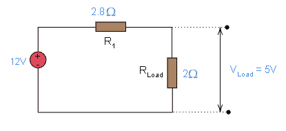
- 2 Ohm load resistance
- 12V DC power supply
- 5V load voltage
We need to step down the 12V battery’s voltage to supply the load with 5V. So, we can place a 2.8-ohm resistor in series with the load to provide the required voltage.
Calculate the Efficiency of a DC-DC Converter
We can calculate the efficiency of the circuit as follows:
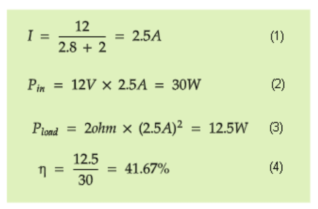
From these calculations, we can see that the load consumes only 12.5W of the input power. The remaining part (30 – 12.5 = 17.5 W) is converted into heat.
Now, this is too wasteful. If you touch the series resistor, it will be hot, and you may need to incorporate mechanisms to cool down your circuitry. As an attempt to obtain a more efficient solution, take a look at the circuit shown in the diagram below:
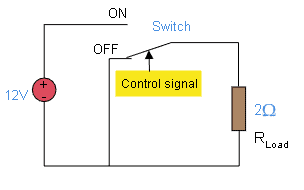
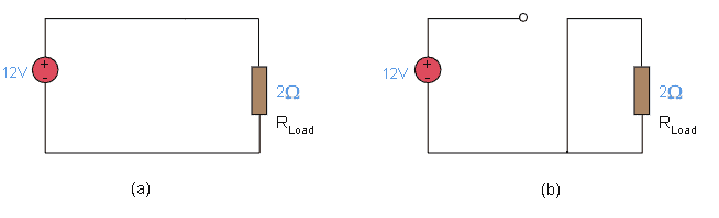
When the switch is OFF, the input voltage is 0V, and when the control is at the ON position, the input voltage is 12V. The diagram below shows the equivalent circuits for switch positions ON and OFF, respectively.
If we control the switch as shown in diagram (a) below, we obtain a voltage graph as shown in diagram (b) below. T is the switching period, and its units are in milliseconds or microseconds.
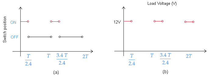
In this case, the average output voltage of this switching behavior is 5V since:
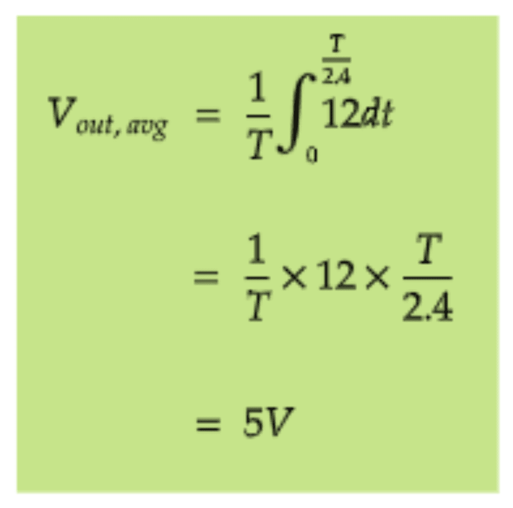
The average output voltage of this circuit is 5V, but we can improve the output waveform by using RC filter circuits to get rid of harmonics.
If we assume the switch to be ideal (an ideal switch is a switch that does not consume or dissipate power from the source), we can calculate the efficiency of this circuit to be 100%. When the switch is at position ON, the current flowing through the circuit is 6A. Since we have an ideal switch, the dissipated power is P_diss = RI2 = 0 * 92 = 0W. When the switch is at position OFF, no current flows through the switch, so in this case, the dissipated power is 0, too.
In a real-world scenario, however, it may be challenging to find an ideal switch. This means in reality there will be some power dissipated, but the conversion efficiencies are high despite these dissipations.
Boost Converters
Boost converters increase the voltage of a power source. For example a boost converter could take a 5V power source and boost it up to 25V. Typically, you find DC-DC boost converters in battery chargers or solar panels. They can also be used to supply components with different operating voltages from the same battery.
This configuration steps up the DC voltage to a level determined by the choice of components in your circuit. Here is a general schematic of a boost converter.
The basic configuration consists of a DC power source (Vin), an inductor (L), a diode (D), a switching device (SW), a smoothing capacitor (C), and the load resistance (Load). Vout is the output voltage.
The switch is typically a power electronics device such as a MOSFET or BJT transistor controlled by a PWM signal. This PWM signal works by switching the transistor very fast, usually thousands of times per second.
How Boost Converters Work
To understand how a boost converter works, let’s first understand how an inductor works.
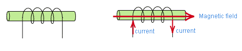
Recall that an inductor is a passive electronic component that can store electrical energy in the form of magnetic energy. We can use this property to control the output voltage of our circuit. Here is how it works:
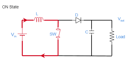
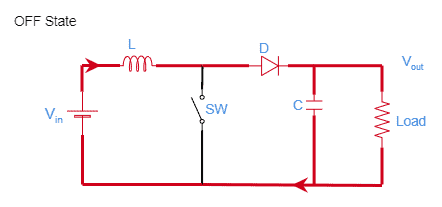
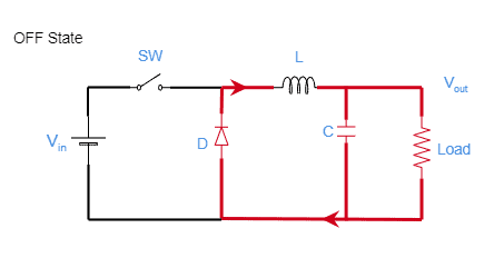
- If we OPEN the switch, as shown in the “Boost switch OFF State” diagram above, a smaller current flows from the battery, through the inductor, through the diode and charging the capacitor.
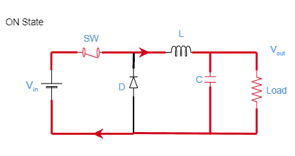
- When we CLOSE the switch, as shown in the “Boost switch ON State” diagram above, a larger current will flow from the battery, through the inductor and through the switch because we now have a path of least resistance. Now, the inductor behaves interestingly. Since we now have a larger value of current flowing through the circuit, the magnetic field of the inductor will expand. This means that the inductor is storing energy, and during this process, the potential across the inductor will be positive on the left and negative on the right.
- When we OPEN the switch again, the current flowing through the circuit will no longer be a large current due to the high impedance. When the current flowing through the circuit decreases, the magnetic field across the inductor will collapse. In the process, the electrical energy that was stored is now being released. This causes the polarity of the inductor to change. We now have a negative polarity on the left side and positive on the right side of the inductor. If you look closely, the inductor is now in series with the battery.
The current through an inductor cannot change instantaneously. Therefore, the inductor will try to support that change by generating a large voltage. This means that we now have the voltage generated by the inductor and the voltage from the battery at the capacitor. Suppose we keep turning the switch ON and OFF. We will have an output voltage that is higher than the battery voltage.
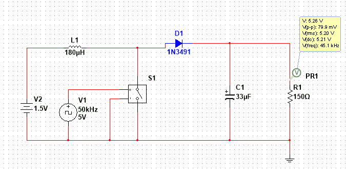
How to Build a Boost Converter
In this project we build a 1.5V to 5V DC-DC Boost converter. Here are the components that you need if you want to build this circuit:
- 1.5V DC power source
- One 180uH inductor
- One 1N3491 diode
- One 33uF capacitor
- One 150 Ohm resistor
- One MOSFET or JFET switching transistor
- A PWM source like an Arduino Uno or 555 timer that can generate a 50KHz, 5V, 75% duty cycle
Here’s the schematic:
Buck Converters
Buck converters reduce the voltage of a power supply. This is a power electronics circuit that steps down the DC voltage to a level determined by the choice of components in your circuit.
Unlike linear regulators that reduce the voltage by dissipating power as heat, buck converters reduce the voltage by increasing the current.
Here is a general schematic of a buck converter.
Note that these are the same components that we find in a boost converter, but their arrangement is different.
How Buck Converters Work
To obtain an output voltage lower than battery voltage, we connect the switch before the inductor. When we turn ON and OFF the switch in this configuration, the average output voltage will be lower than the battery’s voltage.
Here is what happens:
- If the switch (SW) is closed, current will flow through the switch to the circuit. As the current increases, the magnetic field of the inductor will expand. While that happens, the inductor is storing energy in its magnetic field. As before, the polarity of the inductor will be positive on the left and negative on the right. This opposing voltage counteracts the voltage of the source and, therefore, reduces the net voltage across the load.
- When we open the switch, the magnetic field of the inductor will collapse, and the current will flow from the inductor through the diode. This current will add to the current that flows during step one, the OFF state. That is why the average current increases on this type of converter. This also makes up for the reduced voltage, therefore, preserves the power supplied to the load.
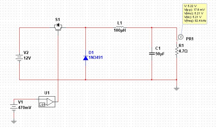
How to Build a Buck Converter
In this project we build a 12V to 5V DC-DC Buck converter. Here are the components that you need if you want to build this:
- 12V DC power source
- One MOSFET or JFET switching transistor
- One 1N3491 diode
- One 100uH inductor
- One 50uF capacitor
- One 4.7 Ohm resistor
- A PWM source like an Arduino or 555 timer
Here is the schematic:
In this tutorial, we learned about the two main types of DC-DC converters – buck converters and boost converters. We also learned how they work and how to build circuits for them. Feel free to leave a comment below if you have any questions!


I am so pleased to learn about dc to dc converters especially about use of inductors. currently iam trying to build a regulator that can convert 48v from a lithium battery to 12v for lighting LED bulbs. What could be the values of the components using an inductor. If possible avail me a complete circuit diagrame.
is there a constant input voltage DC with variable output DC voltage by using DC-Dc boost converter to build my own project where this input volage DC is the output DC voltage from power supply AC-DC converter